


—10—
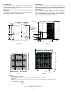
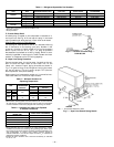
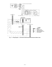
Duplex 575C120, 541A180 with 524A-H240 or 524A-H300
In order to properly connect two heat pump condensing
units to a single 524A-H packaged air handler, it is
necessary to add field-supplied Fan Coil Relay Board(s),
P/N 33ZCRLYBRD. Relay board(s) no. 1 and no. 2 should be
installed in the control box of condensing unit.
IMPORTANT: The common (COM) terminals from the fan
coil relay board(s) must be connected to the ‘C’ terminal in
condensing unit ‘A’.
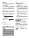
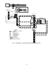
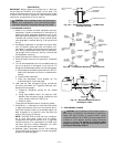
Route thermostat cable or equivalent single leads of
no. 18 AWG (American Wire Gage) colored wire from sub-
base terminals through conduit in unit to low-voltage con-
nections as shown on unit wiring diagram and Fig. 12
and 13.
NOTE: For wire runs up to 50 ft, use no. 18 AWG insulated wire
(35 C minimum). For 51 to 75 ft, use no. 16 AWG insulated
wire (35 C minimum). For over 75 ft, use no. 14 AWG insulated
wire (35 C minimum). All wire larger than no. 18 AWG cannot
be directly connected to the thermostat and will require a junc-
tion box and a splice at the thermostat.
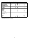
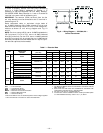
Table 7 — Electrical Data
LEGEND
*Units are suitable for use on electrical systems where voltage supplied
to the unit terminals is not below or above the listed limits.
NOTES:
1. The MCA and MOCP values are calculated in accordance with the
NEC, Article 440.
2. Motor RLA and LRA values are established in accordance with
Underwriters’ Laboratories (UL), Standard 1995.
3. The 575-v units are UL, Canada-listed only.
4. Convenience outlet is available as either a factory-installed option
or a field-installed accessory and is 115-v, 1 ph, 60 Hz.
UNIT
FACTORY-
INSTALLED
OPTION
NOMINAL VOLTAGE
(V-Ph-Hz)
VOLTAGE RANGE* COMPRESSOR FAN MOTORS POWER SUPPLY
Min Max RLA LRA FLA MCA MOCP
575B 072 NONE
208/230-3-60 187 253 18.9 146 5.1 28.7 45
460-3-60 414 506 9.5 73 2.6 14.5 20
575-3-60 517 633 7.6 58 1.2 10.7 15
575C
090
NONE OR DISCONNECT
208/230-3-60 187 254 29.0 190 1.5
39.0 60
CONVENIENCE OUTLET 43.8 60
NONE OR DISCONNECT
460-3-60 418 506 15.0 95 0.7
19.8 30
CONVENIENCE OUTLET 21.9 30
120
NONE OR DISCONNECT
208/230-3-60 187 254 34.0 225 1.5
45.0 60
CONVENIENCE OUTLET 50.0 70
NONE OR DISCONNECT
460-3-60 418 506 17.0 114 0.7
23.0 30
CONVENIENCE OUTLET 25.0 30
NONE OR DISCONNECT
575-3-60 523 632 14.0 80 0.7
18.0 25
CONVENIENCE OUTLET 20.0 25
541A 180 NONE
208/230-3-60 187 253 63.6 266 4.3 87.5 125
460-3-60 414 528 29.3 120 2.3 40.7 60
575-3-60 518 660 23.8 96 1.8 33.0 50
FLA — Full Load Amps
LRA — Locked Rotor Amps
MCA — Minimum Circuit Amps
MOCP — Maximum Overcurrent Protection
NEC — National Electrical Code
RLA — Rated Load Amps
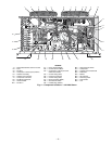
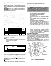
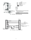
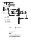
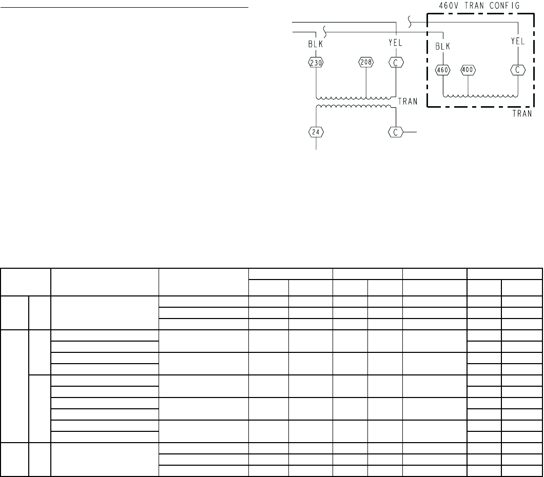
Fig. 8 — Wiring Diagram — 575C090,120 —
Control Transformer