


—5—
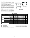
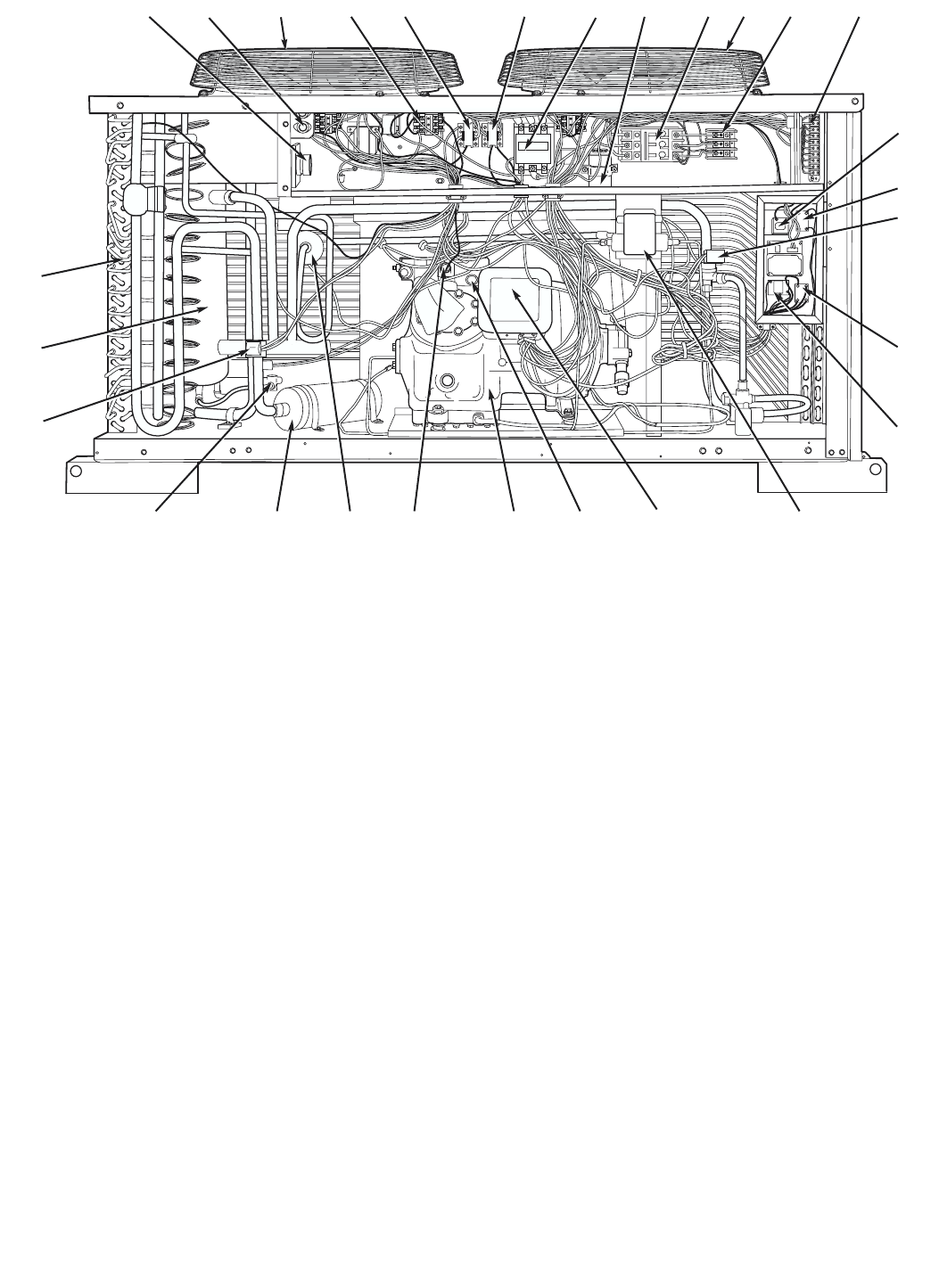
LEGEND
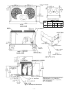
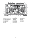
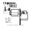
Fig. 4 — Component Locations — 541A180 Shown
1— Defrost Board/Time Guard II Control 11 — Power Terminal Block 20 — High-Pressure Switch
2— Fuse 12 — Control Terminal Block 21 — Compressor
3— Fan No. 1 13 — Compressor Lockout (CLO2 for
Crankcase Heater)
22 — Capacity Control Solenoid
4— Compressor Lockout (CLO) Device 23 — Filter Drier
5— Outdoor-Fan Relay 14 — Control Relay (CR3) 24 — Muffler
6— Outdoor-Fan Contactor 15 — Liquid Line Solenoid 25 — Oil Solenoid
7— Compressor Contactor 16 — Control Relay (CR2) 26 — Reversing Valve
8— Fan Motor Capacitors 17 — No Dump Relay (NDR) 27 — Accumulator
9— Circuit Breaker 18 — Oil Pressure Switch 28 — Coil
10 — Fan No. 2 19 — Fusible Plug (hidden)
12 3 45 6 78 9101112
13
14
15
16
17
18
19202122232425
26
27
28