


—7—
III. COMPLETE REFRIGERANT PIPING CONNECTIONS
Refrigerant lines must be carefully designed and constructed
to ensure equipment reliability and efficiency. Line length,
pressure drop, compressor oil return, and vertical separation
are several of the design criteria that must be evaluated. See
Table 2.
IMPORTANT: Do not bury refrigerant piping underground.
IMPORTANT: Piping must be properly sized and installed for
the system to operate efficiently.
A. Check Vertical Separation
If there is any vertical separation between the indoor and out-
door units, check to ensure that the separation is within
allowable limits. Relocate equipment if necessary. See Table 3.
B. Refrigerant Line Sizing
Consider the length of the piping required between the out-
door and indoor units. The maximum allowable line length is
100 ft. See Table 3. Refrigerant suction piping should be
insulated.
IMPORTANT: A refrigerant receiver is not provided with the
unit. Do not install a receiver.
IMPORTANT: For 575C090,120 applications with liquid lift
greater than 20 ft, use
5
/
8
-in. liquid line. Maximum lift is
60 ft.
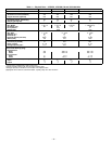
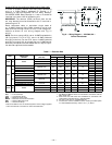
Table 2 — Refrigerant Piping Sizes
*If there is a vertical separation between indoor and outdoor units, see
Table 3 — Maximum Vertical Separation.
LEGEND
L — Liquid Line V — Vapor Line
NOTES:
1. Pipe sizes are based on a 2 F loss for liquid and vapor lines.
2. Pipe sizes are based on the maximum linear length, shown for each
column, plus a 50% allowance for fittings.
3. Charge units with R-22 refrigerant in accordance with unit installation
instructions.
4. Maximum line length must not exceed 100 ft.
5. Do not bury refrigerant piping.
Table 3 — Maximum Vertical Separation*
*Vertical distance between indoor and outdoor units.
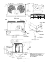
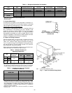
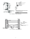
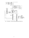
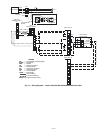
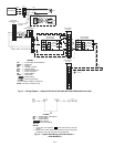
C. Install Filter Drier(s) and Moisture Indicator(s)
Every unit should have a filter drier and liquid-moisture
indicator (sight glass). In some applications, depending on
space and convenience requirements, it may be desirable to
install 2 filter driers and sight glasses. One filter drier and
sight glass may be installed at A
locations in Fig. 5. If
desired, 2 filter driers and sight glasses may be installed at
B
locations in Fig. 5.
Select the filter drier for maximum unit capacity and minimum
pressure drop. Complete the refrigerant piping from indoor
unit to outdoor unit before opening the liquid and vapor lines at
the outdoor unit. For specific filter driers see Table 4.
D. Liquid Line Piping Procedure
Pipe the system liquid line as follows:
1. Open service valves in sequence:
a. Discharge service valve on compressor.
b. Suction service valve on compressor.
c. Liquid line valve.
2. Remove
1
/
4
-in. flare cap from liquid valve Schrader
port.
3. Attach refrigerant recovery device and recover hold-
ing charge.
4. Remove runaround loop (581A180 only).
5. Connect system liquid line from liquid connection of
outdoor unit (575B,C, 541A) to indoor unit (524A-H)
liquid line connections. Select proper field-supplied
bi-flow filter driers and install in the liquid line. See
Fig. 5. Install a field-supplied liquid moisture indica-
tor between the filter drier(s) and the liquid connec-
tions on the indoor unit. Braze or silver alloy solder
all connections. Pass nitrogen or other inert gas
through piping while making connections to prevent
formation of copper oxide. (Copper oxides are
extremely active under high temperature and pres-
sure. Failure to prevent collection of copper oxides
may result in system component failures.)
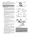
E. Liquid Line Solenoid Valve
Addition of a liquid solenoid valve (LLSV) is required (except
for 541A180 units that already have LLSV factory-installed).
The LLSV must be a bi-flow type suited for use in heat pump
systems. Refer to Table 4. Wire the solenoid valve in parallel
with the compressor contactor coil.
The LLSV must be installed at the outdoor unit with the
flow arrow pointed toward the outdoor unit (in-flow direction
for the Heating mode).
OUTDOOR
UNIT
LENGTH OF PIPING ft
MAXIMUM
LIQUID
LINE
(in. OD)*
0-25 26-60 61-100
Line Size (in. OD)
LVLVLV
575B072
1
/
2
1
1
/
8
5
/
8
1
1
/
8
5
/
8
1
1
/
8
5
/
8
575C090
3
/
8
1
1
/
8
1
/
2
1
1
/
8
1
/
2
1
1
/
8
5
/
8
575C120
1
/
2
1
3
/
8
1
/
2
1
3
/
8
1
/
2
1
3
/
8
5
/
8
541A180
5
/
8
1
5
/
8
3
/
4
1
5
/
8
3
/
4
1
5
/
8
3
/
4
OUTDOOR
UNIT
INDOOR UNIT
524A-H
DISTANCE FT
Outdoor Unit
Above 524A-H
575B 072 090 50
575C
090 090 60
120 120 60
541A 180 180 80
WARNING: Unit is pressurized with a holding
charge of refrigerant. Recover R-22 holding charge
before removing runaround liquid piping loop. Failure
to recover holding charge before removing piping loop
could result in equipment damage and personal injury.
LEGEND
Fig. 5 — Location of Sight Glass(es)
and Filter Driers
TXV — Thermostatic Expansion Valve