


—18—
SEQUENCE OF OPERATION
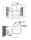
I. 575B072 UNITS
When power is supplied to unit, the transformer (TRAN) and
crankcase heater (CCH) are energized.
A. Cooling
On a call for cooling, the thermostat completes the following
circuits: R-G, R-Y, and R-O. If the compressor recycle delay of
3 minutes is complete, the compressor and outdoor fan start.
The reversing valve is energized for cooling and the indoor-
fan motor starts.
When the thermostat is satisfied, the circuits are opened,
and the compressor, outdoor-fan motor, and indoor-fan motor
stop. The reversing valve is deenergized.
B. Heating
On a call for heating, the thermostat completes the following
circuits: R-G and R-Y. If the compressor recycle delay of
3 minutes is complete, the compressor and outdoor fan start.
The indoor-fan motor will also start.
If room temperature continues to fall, the thermostat
completes circuit R-W. If the optional electric heat package is
used, the heat relay is energized, and the electric heaters are
energized.
When the thermostat is satisfied, the circuits are opened,
and the compressor, outdoor-fan motor, heaters, and indoor-
fan motor stop.
C. Defrost
Defrost board (DB) is a time and temperature control, which
includes a field-selectable time period between checks for
frost (30, 50, and 90 minutes). Electronic timer and defrost
cycle start only when contactor is energized and defrost ther-
mostat (DFT) is closed (below 28 F).
Defrost mode is identical to Cooling mode, except outdoor-fan
motor (OFM) stops and a bank of supplemental electric heat
turns on to warm air supplying the conditioned space.
Defrost mode is terminated when the DFT reaches 65 F.
D. Air Circulation
When the fan switch is at FAN ON, the indoor-air fans oper-
ate continuously to provide ventilation. The thermostat
operates the other components as described above.
E. Emergency Heat Cycle
If the compressor is inoperative due to a tripped safety
device, the second stage of the thermostat automatically
energizes the indoor-air fan and the electric resistance heat-
ers (if equipped).
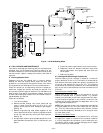
II. 575C090,120 UNITS
When power is supplied to unit, the transformer (TRAN) is
energized. The crankcase heater is also energized.
A. Cooling
With the thermostat subbase in the cooling position, and
when the space temperature comes within 2° F of the cooling
set point, the thermostat makes circuit R-O. This energizes
the reversing valve solenoid (RVS) and places the unit in
standby condition for cooling.
As the space temperature continues to rise, the second stage
of the thermostat makes, closing circuit R-Y. When compres-
sor time delay (5 ± 2 minutes) is completed, a circuit is made
to contactor (C), starting the compressor (COMP) and
outdoor-fan motor (OFM). Circuit R-G is made at the same
time, energizing the indoor-fan contactor (IFC) and starting
the indoor-fan motor (IFM) after one-second delay.
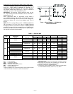
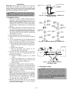
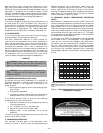
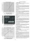
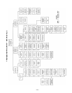
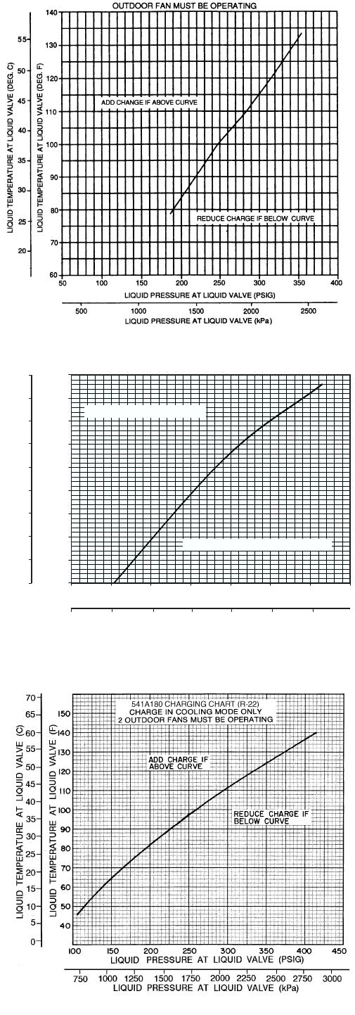
Fig. 19A — 575B072 Charging Chart
Fig. 19B — 575C090,120 Charging Chart
50
LIQUID PRESSURE AT LIQUID VALVE (PSIG)
LIQUID TEMPERATURE AT LIQUID VALVE (F)
344
LIQUID PRESSURE AT LIQUID VALVE (Kilopascals)
ADD CHARGE IF ABOVE CURVE
REDUCE CHARGE IF BELOW CURVE
50
60
70
80
90
100
110
120
130
140
100
150 200 250 300 350 40
0
689
1034
1379
1724
2069
2414
LIQUID TEMPERATURE AT LIQUID VALVE (C)
10
16
21
27
32
38
43
49
54
60
Fig. 19C — 541A180 Charging Chart