


—11—
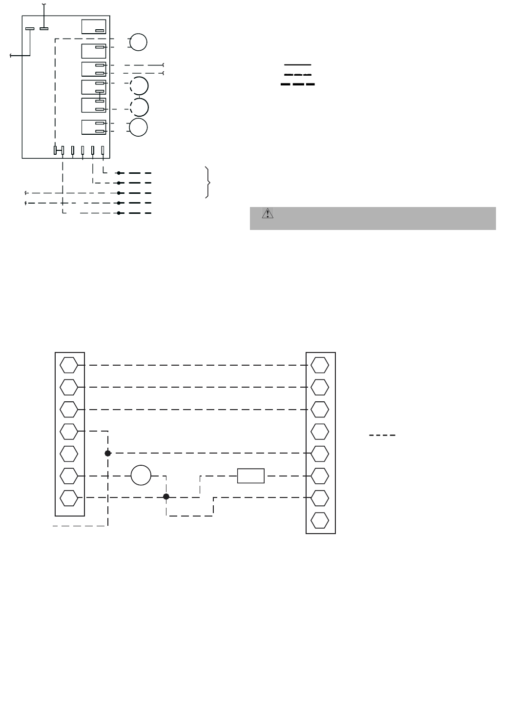
W2
G
C
R
Y
O
E
1
2
3
4
5
6
7
8
TO ELECTRIC
HEATER
ACCESSORY,
IF EQUIPPED
IFC
LLSV
THERMOSTAT
CONNECTION
BOARD (TB)
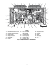
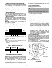
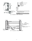
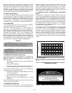
Fig. 9 — Wiring Diagram — 575B072; 208/230-3-60 Units
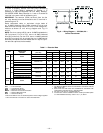
LEGEND
DF — Defrost Relay
LP/HP — Low or High-Pressure Switch (Optional)
PS — Pressure Switch
RV — Reversing Valve
SEN — Outdoor Coil Temperature Sensor
TSTAT — Thermostat
Line Voltage Factory
Low Voltage Factory
Low Voltage Field
COLOR CODE
NOTES:
1. All electrical work must be done in conformance with the National
Electrical Code (NFPA No. 70) and in conformance with local
codes and authorities having jurisdiction.
2. For use with copper conductors only.
BK Black
BL Blue
O Orange
R Red
W White
Y Ye l l o w
CAUTION: Not suitable for use on systems exceeding
150 volts to ground.
RV
Y
BK
Y
CC
BL
BK
PS2
Y
DF
C
PS1
O
WR
BK
Y-RV
DEFROST
CONTROL
BK
BL
R-RV
FAN
RV
COIL
SEN
DEFROST HEAT
COMPRESSOR
HEAT/COOL
COMMON
W
Y
O
BL
LP/HP
LP/HP
FROM
TSTAT
24 VAC
R
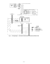
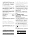
LEGEND
IFC — Indoor Fan Contactor
LLSV — Liquid Line Solenoid Valve
TB — Terminal Block
Field Wiring
NOTES:
1. For thermostat and subbase part no. see
price pages.
2. Use copper conductors only.
Fig. 10 — Wiring Diagram — 575C090,120; 230-3-60 Units