


—2—
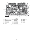
B. Locate Unit
For service access and unrestricted airflow, provide clearance
on each end and side of unit. Position unit so that there is
unrestricted airflow above unit.
NOTE: Before mounting unit, remove holddown brackets and
release skid.
If conditions or local codes require unit to be fastened to pad,
use the mounting holes in the base rails.
C. Mount Unit
The unit may be mounted on a solid, level concrete pad, on
accessory mounting legs, or on field-supplied raised supports
at each mounting position. (Note that mounting hardware is
field supplied.)
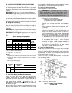
Bolt unit securely to pad or supports after unit is in position
and is level. Be sure to mount unit level to ensure proper oil
return to compressors. Mounting holes on unit can be used to
secure unit to vibration isolators, if required.
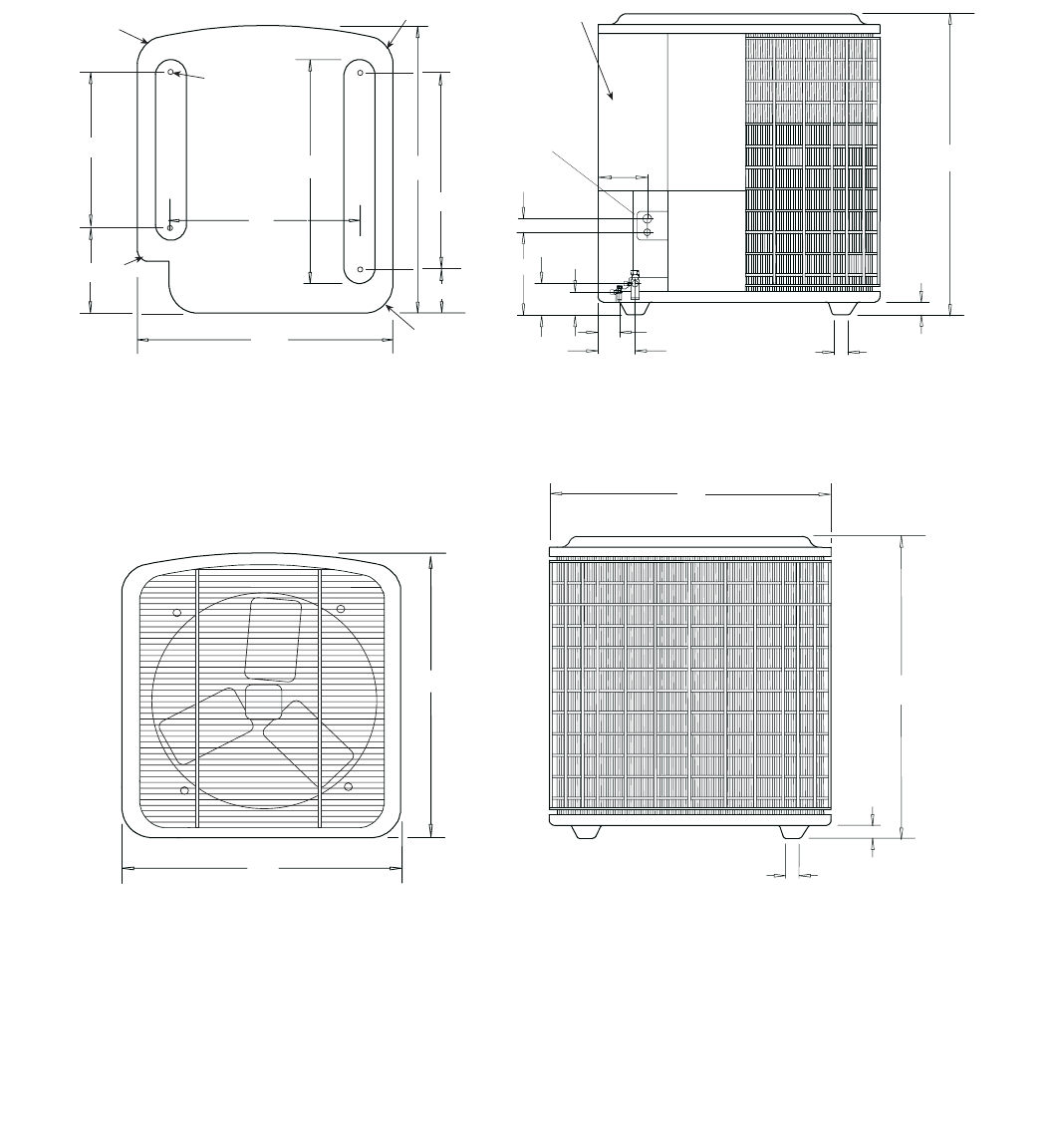
1-1/2
38-1/2
1-1/2
TOP FRONT
33
35
33
38-1/2
Line & Low
Voltage Wiring
Entrances
1-1/2
1-1/2
4-1/4
2-1/2
1-1/8
2-1/8
5-3/4
9-3/4
1-1/2
BOTTOM
REAR
27
24
33
35
A
B
D
C
7/8
4 PLACES
24 1/2
10
19 3/8
4 7/8
FRONT
CONTROL BOX
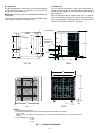
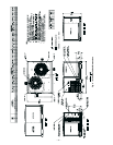
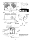
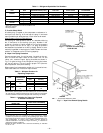
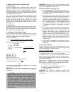
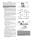
Fig. 1 — 575B072 Unit Dimensions
NOTES:
1. All dimensions are in inches.
2. Recommended clearance for proper airflow (local codes or jurisdictions may prevail):
Top — 60 in.
Sides — 24 in. on 3 sides, one side may be 6 in. (Control box side should have 24-in. clearance for service
access.)
3. Corner Weights (lb): A = 86
B = 84
C = 92
D = 90