


—16—
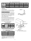
Before starting the unit, charge liquid refrigerant into the
high side of the system through the liquid service valve.
Allow high and low side pressures to equalize before starting
compressor. If pressures do not equalize readily, charge
vapor on low side of system to assure charge in the evapora-
tor. Refer to GTAC II, Module 5, Charging, Recovery, Recy-
cling, and Reclamation for liquid charging procedures.
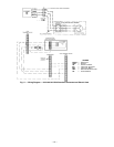
III. LIQUID LINE SOLENOID
To minimize refrigerant migration to the compressor during
the heat pump OFF cycle, the 575B,C unit must have a
bi-flow liquid line solenoid valve (field supplied). The valve
opens when the compressor is energized, and closes when
the compressor is deenergized. This reduces compressor
flooded starts, thus significantly increasing compressor life.
IV. ACCUMULATOR
The unit accumulator controls the rate of liquid refrigerant
to the compressor during heat pump operation.
The 541A accumulator features a unique method for
returning oil to the compressor. The oil return mechanism is
external to the accumulator. The mixture of oil and refriger-
ant is metered to the compressor by a brass orifice which is
removable and cleanable. The oil return mechanism also
contains a solenoid valve that opens when the compressor is
ON and closes when the compressor is OFF. This keeps the
liquid refrigerant stored in the accumulator from draining to
the compressor during the heat pump OFF cycle, which
further protects the compressor against flooded starts.
START-UP
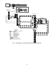
I. COMPRESSOR ROTATION (575B,C Units)
On 3-phase units with scroll compressors, it is important to
be certain compressor is rotating in the proper direction. To
determine whether or not compressor is rotating in the
proper direction:
1. Connect service gages to suction and discharge pres-
sure fittings.
2. Energize the compressor.
3. The suction pressure should drop and the discharge
pressure should rise, as is normal on any start-up.
If the suction pressure does not drop and the discharge
pressure does not rise to normal levels:
1. Note that the condenser fan is probably also rotating
in the wrong direction.
2. Turn off power to the unit, tag disconnect.
3. Reverse any two of the unit power leads.
4. Reapply power to the compressor, verify correct
pressures.
The suction and discharge pressure levels should now move
to their normal start-up levels.
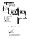
II. COMPRESSOR OVERLOAD
This overload interrupts power to the compressor when
either the current or internal motor winding temperature
becomes excessive, and automatically resets when the
internal temperature drops to a safe level. This overload
usually resets within 60 minutes (or longer). If the internal
overload is suspected of being open, disconnect the electrical
power to the unit and check the circuit through the overload
with an ohmmeter or continuity tester.
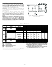
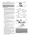
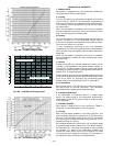
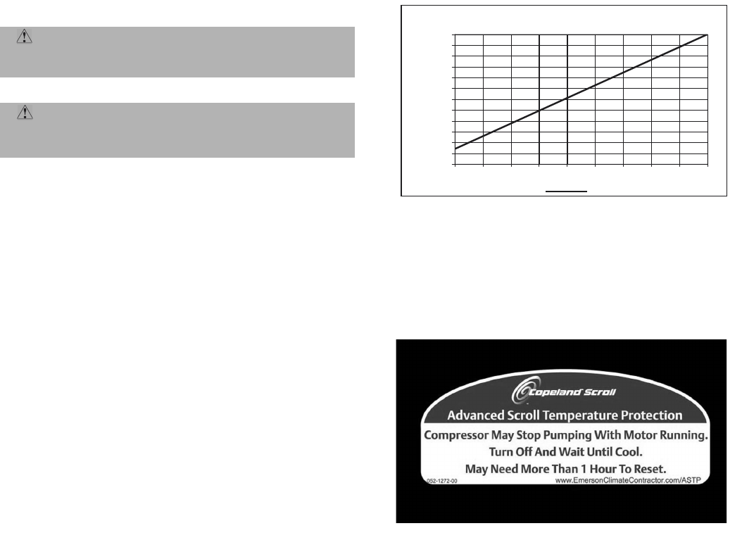
III. ADVANCED SCROLL TEMPERATURE PROTECTION
(ASTP)
Advanced Scroll Temperature Protection (ASTP) is a form of
internal discharge temperature protection that unloads the
scroll compressor when the internal temperature reaches
approximately 300 F. At this temperature, an internal bi-
metal disk valve opens and causes the scroll elements to sep-
arate, which stops compression. Suction and discharge pres-
sures balance while the motor continues to run. The longer
the compressor runs unloaded, the longer it must cool before
the bi-metal disk resets. See Fig. 17.
To manually reset ASTP, the compressor should be stopped
and allowed to cool. If the compressor is not stopped, the
motor will run until the motor protector trips, which occurs
up to 90 minutes later. Advanced Scroll Temperature Protec-
tion will reset automatically before the motor protector
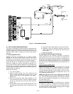
resets, which may take up to 2 hours. A label located above
the terminal box identifies Copeland Scroll compressor
models (ZR94, 108 and 125) that contain this technology. See
Fig. 18.
CAUTION: Compressor crankcase heater must be
on for 24 hours before start-up. After the heater has
been on for 24 hours, the unit can be started.
CAUTION: Prior to starting compressor, a preliminary
charge of refrigerant must be added to avoid possible
compressor damage.
0
10
20
30
40
50
60
70
80
90
100
110
120
0 102030405060708090
Compressor Unloaded Run Time (Minutes)
Recommended Cooling Time
(Mi
nut
es)
*Times are approximate.
NOTE: Various factors, including high humidity, high ambient tempera-
ture, and the presence of a sound blanket will increase cool-down
times.
Fig. 17 — Recommended Minimum Cool-Down Time After
Compressor is Stopped*
Fig. 18 — Advanced Scroll Temperature Protection Label