


6
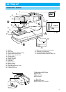
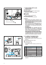
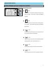
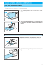
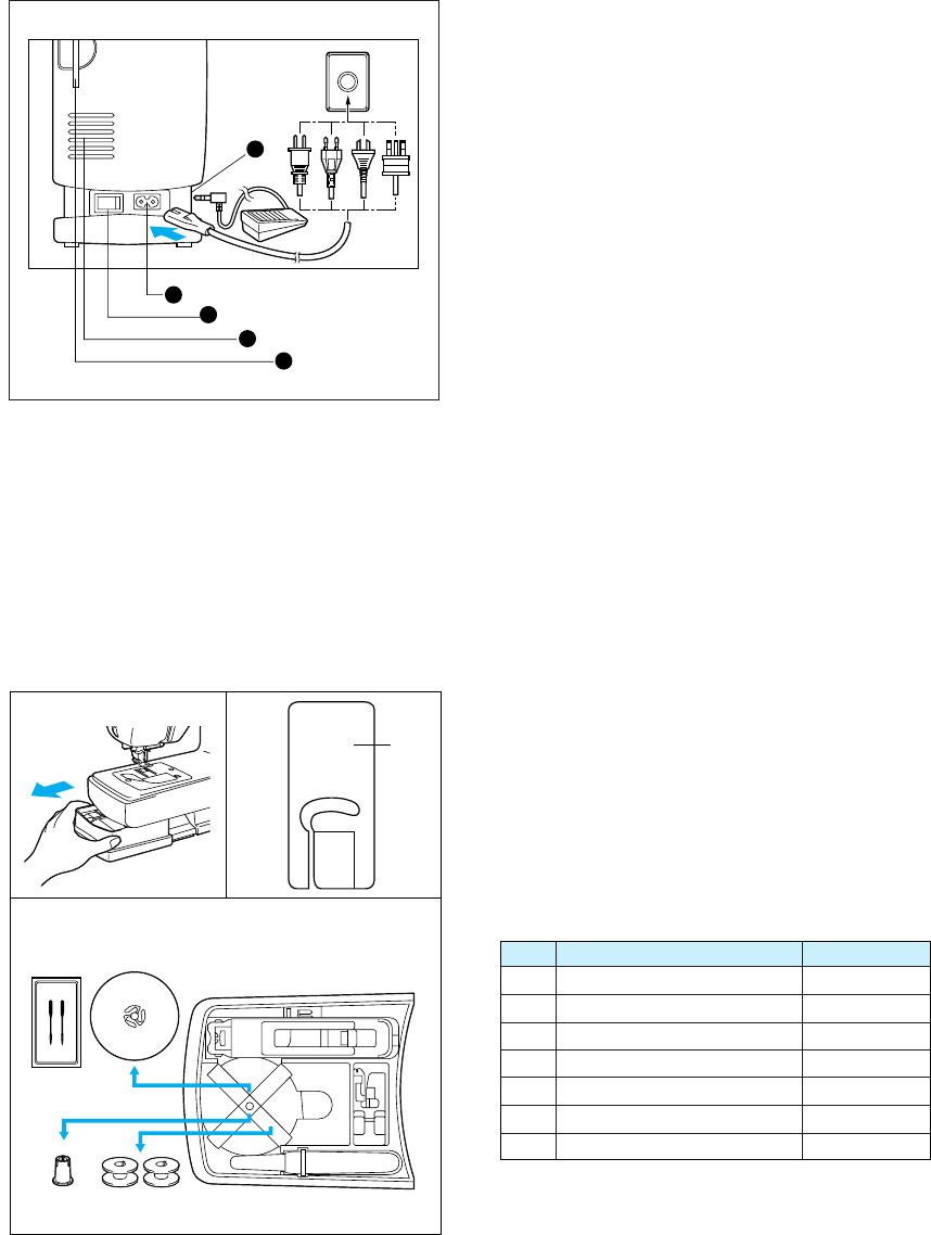
A. MAIN POWER SWITCH AND
CONNECTORS
1 Power socket
Use to connect machine to power supply.
2 Main power switch
Use to turn on/off the main power.
3 Air vents
4 Card slot
Slot for memory card insertion.
5 Foot controller jack
Use to connect the foot controller.
CAUTION
– When leaving the sewing machine unat-
tended, the main switch of the machine must
be switched off or the plug must be removed
from the socket-outlet.
– When servicing the sewing machine, or
when removing covers or changing bulbs,
the machine or the electrical set must be
unplugged.
– For U.S.A. only
This appliance has a polarized plug (one
blade wider than the other). To reduce the
risk of electric shock, this plug is intended
to fit in a polarized outlet only one way.
If the plug does not fit fully in the outlet, re-
verse the plug. If it still does not fit, contact
a qualified electrician to install the proper
outlet. Do not modify the plug in any way.
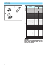
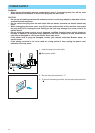
B. FLATBED ATTACHMENT WITH
ACCESSORY COMPARTMENT
I Slide accessory case to the left and out of the
machine.
II Each presser foot has a letter.
1 Presser foot letter
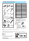
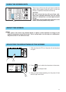
III ACCESSORY LIST
The location of each accessory is shown in fig-
ure III.
J
1
6
7
1
3
2
4
5
III
III
1 Buttonhole foot “A” X57789-101
2 Overcasting foot “G” X51162-001
3 Seam ripper X54243-001
4 Bobbin X80309-001
5 Needle set XA6627-001
6 Spool cap (Large) 130012-053
7 Spool cap (Small) XA5752-001
No. Part Name Part Code
* Always use BROTHER accessories with this
machine.