


3. INSTALLATION
11
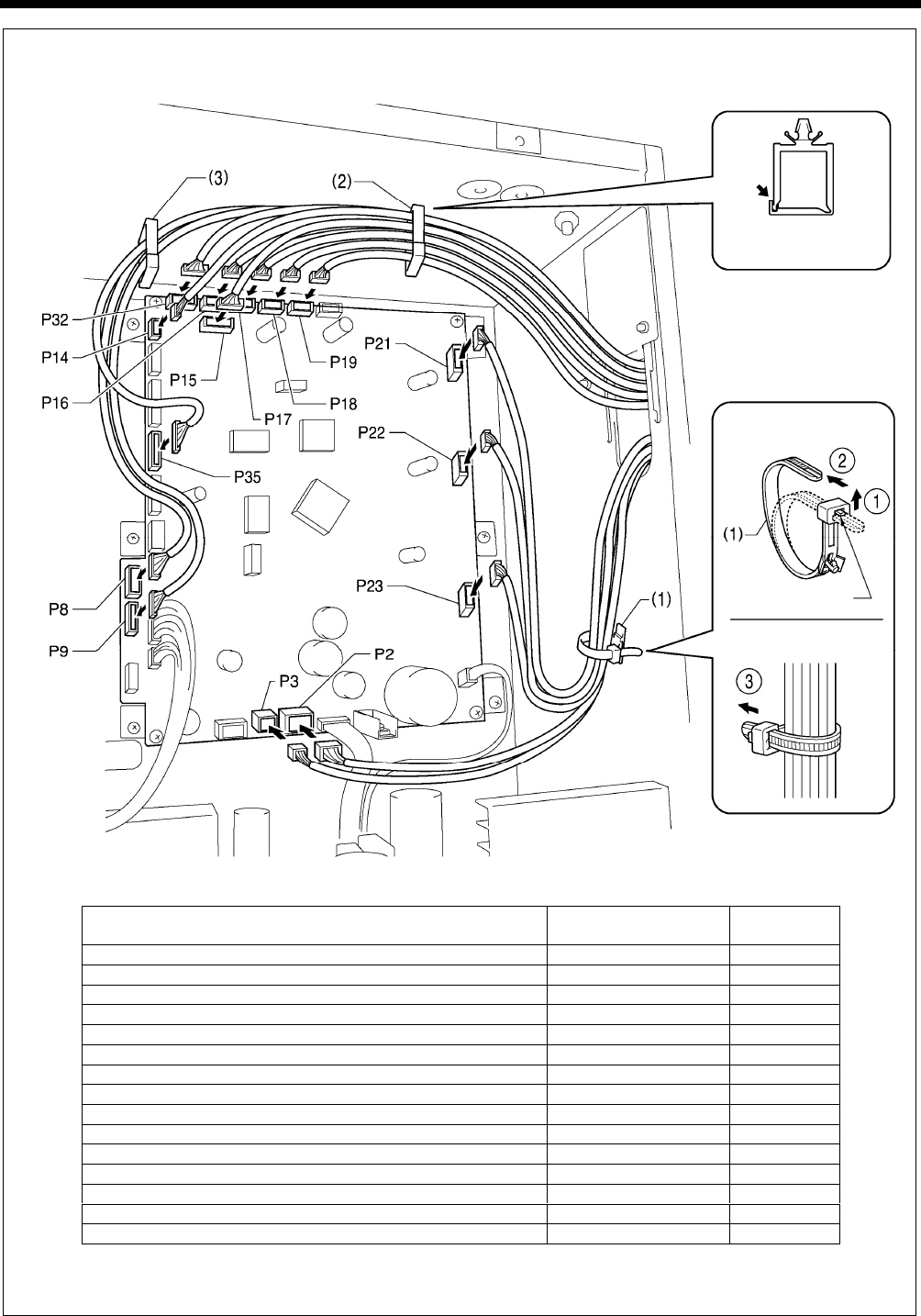
BAS-311H
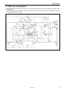
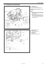
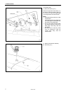
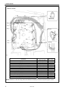
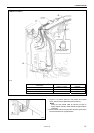
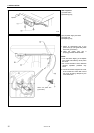
NOTE: Route the X, Y and work clamp pulse motor harnesses so that they do not touch the power supply P.C. board.
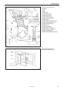
Connectors
Connection location on
main P. C. board
Cord clamps
X pulse motor encoder [5-pin] White P17 (X-ENC) (2)
Y pulse motor encoder [5-pin] Blue P18 (Y-ENC) (2)
Work clamp pulse motor encoder [5-pin] Black P19 (P-ENC) (2)
Machine head switch [3-pin] P14 (HEAD-SW) (2)
Conversion harness (two-pedal foot switch) [7-pin] White P15 (PEDAL) (2)
Machine head memory [6-pin] P16 (HEAD-M) (2)
Thread trimmer solenoid [6-pin] P2 (SOL1) (1)
Tension release solenoid [4-pin] P3 (SOL2) (1)
X pulse motor [4-pin] White P21 (XPM) (1)
Y pulse motor [4-pin] Blue P22 (YPM) (1)
Work clamp pulse motor [4-pin] Black P23 (PPM) (1)
Operation panel [8-pin] Red P32 (PROGRAMMER) (2)
Home position sensor [12-pin] White P8 (SENSOR1) (2) (3)
STOP switch [6-pin] White P9 (HEAD) (2) (3)
Valve harness [12-pin] (pneumatic work clamp specifications) P35 (EX-OUT1) (2) (3)
3261B
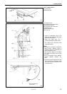
< Main P. C. board >
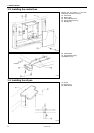
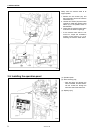
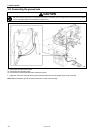
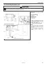
Lock the cord
clamp securely.
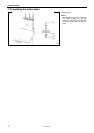
<Removal>
Press
the tab.
<Securing>