


Remote Command Center Wiring | en 9
Bosch Security Systems, Inc. Installation and Operation Guide F.01U.078.098 | 3.0 | 2011.11
5 Wiring
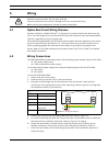
5.1 Option Bus Circuit Wiring Distance
Use four conductor, 18 AWG (0.8 mm
2
) or larger wire to connect Option Bus devices to the
FACP. The total length of wire connected to the Option Bus terminals must not exceed 4000 ft
(1219 m), regardless of the wire gauge used.
The maximum length between any one device and the panel terminals depends on the current
drawn on the branch that the device is on. The current draw on a particular branch can be
found by adding together the individual current draws of each device connected to the
branch. Refer to FPA-1000 Installation and Operation Guide (P/N F.01U.173.607) for detailed
wire length calculations.
5.2 Wiring Connections
The FMR-1000-RCMD is powered by either of the following power outputs from the FPA-1000:
– 12 V DC power (Option bus)
– 24 V FWR unfiltered Aux power output
or UL listed external power supply with common reference ground with the FPA-1000:
– 12 V DC power
– 24 V DC power.
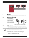
To wire the FMR-1000-RCMD:
1. Power down the control panel.
2. Route the wiring from the FACP to the annunciators.
3. Bring the wiring through one of the knockouts in the annunciator’s base (surface
mounting) or the 3 gang electrical box (flush mounting). Refer to Figure 4.2 on Page 8 for
wire entrance location in the back box.
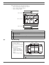
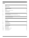
4. Connect the wiring to the FMR-1000-RCMD terminals. Refer to Figure 5.1.
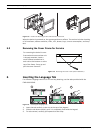
5. For surface mounting with back box: Secure the base. Use the bubble level to make sure
that the back box is perfectly horizontal. Refer to Figure 4.2 on Page 8.
6. Fasten the annunciator unit with the four mounting screws using a Phillips (cross-
headed) screwdriver. Secure the screw for the earth ground connection. Refer to
7. Place the cover frame onto the base along the top side. Press the bottom part until it
snaps into place.
DANGER!
Explosion and burn hazard. Do not short terminals.
Incorrect connections can result in damage to the unit and personal injury.
Before servicing this equipment, remove all power connections.
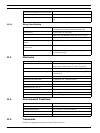
Legend
Figure 5.1 Wiring Connections
GND Ground
V+/PWR Power supply
Y Yellow, Data OUT
G Green, Data IN
P3 Power supply
connection
P7 Data connection
P7
P3
YGGNDPWR+
G
Y
R
B