Remote Command Center Mounting | en 7
Bosch Security Systems, Inc. Installation and Operation Guide F.01U.078.098 | 3.0 | 2011.11
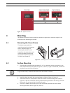
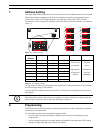
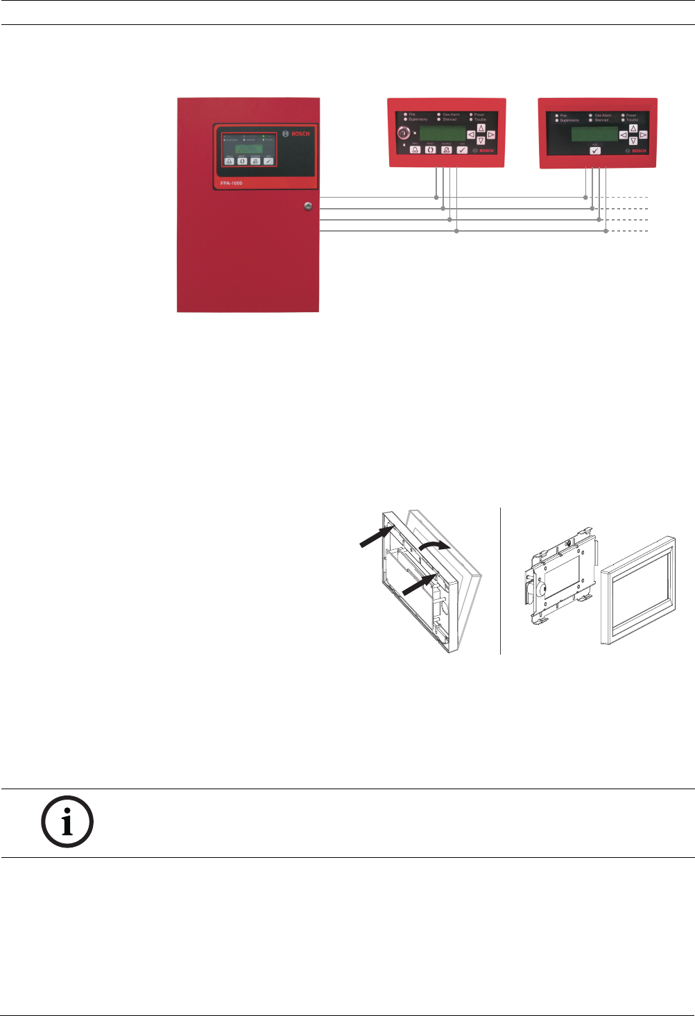
Figure 3.1 System Overview
4 Mounting
The Remote Command Center should be mounted no higher than shoulder height of the
shortest person operating the system.
4.1 Removing the Cover Frame
4.2 Surface Mounting
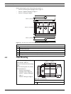
1. The back box provides three knockouts for 1/2 in. diameter conduit connectors in the
back, bottom and top side (refer to Figure 4.2, Item 1). To get a clean break, remove the
knockout from the inside of the box.
2. Install the back box with the arrow pointing up (refer to Figure 4.2, Item 2).
3. Use the back box as a template to mark the location of the mounting holes (refer to
Figure 4.2, Item 3). Provide an opening in the mounting surface for the wiring. Pre-start
the screws. Do not secure the screws at this point.
4. The built-in bubble level allows you to level horizontally without extra tools when
securing the base (refer to Figure 4.2, Item 4).
FPA-1000 FMR-1000-RCMD FMR-1000-RA
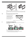
The device comes with the
mounting material and language
tabs in separate bags. For
removing the device’s cover
frame from the annunciator unit,
hold the assembly and unlock
the snap-fit hooks on one side.
Pull the cover frame off.
Figure 4.1 Removing the Cover Frame (before Installation)
NOTICE!
To get a clean break, remove the knockout from the inside of the box.


