


Page 90 P/N: F01U035325-01 Copyright © 2007 Bosch Security Systems, Inc. DS7400Xi (4+) Reference Guide
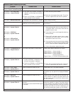
General System Problems (Continued)
Symptom Probable Cause Possible Solution
Power LED is flashing, keypad
displays Control Trouble Press #87.
#87 display = Oct. Relay Fault
#89 display = System Fault 20
#87 display = Multiplex Bus Fault
Can’t reset to factory default.
A control trouble exists.
a) The octal relay module (DS7488) is
defective or the wiring to the module is
defective.
b) There is no DS7488 or a DS7488 has
been removed from the system.
The Multiplex Bus is defective or shorted.
Keypad programming access is set to
PARTIAL from Remote programmer.
Press #87 to determine the trouble condition.
a) Check the wiring to the module.
b) Enter, then exit programming mode. This will re-
scan the options bus and clear the problem.
Check wiring for shorts.
Change setting to FULL from the Remote
programmer.
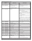
#87 display = RAM Fault
#89 display = System Fault 01
or
#87 display = ROM Fault
#89 display = System Fault 02
or
#87 display = EEProm Fault
#89 display = System Fault 03
The control has failed to communicate.
a) An EEProm fault can be caused by
disconnecting power from the control while it is
in program mode. In this case, enter then exit
program mode to clear.
b) Try to clear the error at the keypad by entering a
PIN then Reset.
c) Remove AC and battery power, then re-apply.
Remember that event history will be lost and
time/date will have to be re-set.
d) If error persists, return the panel to factory default
programming by setting program address 4058
to “01”. If the error clears, re-program the panel.
e) If error still persists, replace the panel.
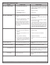
#87 display = Communicator Err
#89 display = Report Failure X
#87 display = 2Ph/Bell Fault
#89 display = System Fault 10
#87 display = Line 1 Fault
#89 display = System Fault 11
#87 display = Line 2 Fault
#89 display = System Fault 12
#87 display = Bell Fault
#89 display = System Fault 13
#87 display = Aux. Output Fault
#89 display = System Fault 14
a) The dual phone line/bell supervision
module (DS7420i) is defective or the
wiring to the module is defective.
b) There is no DS7420i or a DS7420i has
been removed from the system.
There is a phone line fault on line 1.
There is a phone line fault on line 2.
The bell circuit on the DS7420i is open or
shorted.
The auxiliary circuit on the DS7420i is open
or shorted.
Check history #89 to determine the source:
Report Failure 1 = Phone number 1
Report Failure 2 = Phone number 2
Report Failure 3 = Phone number 3
(remote programmer)
Report Failure 4 = DS7416i Communications fault
a)Check the wiring to the module.
b) Enter, then exit programming mode. This will re-
scan the options bus and clear the problem.
Check phone line 1 for proper operation.
Check phone line 2 for proper operation. If you wish
to monitor only one phone line, reprogram address
4021.
Check the bell circuit wiring. Be sure that the end-
of-line resistor is in place. If you don’t wish to use
the bell circuit, place an end-of-line resistor across
the bell terminals.
Check the auxiliary circuit wiring. Be sure that the
end-of-line resistor is in place. If you don’t wish to
use the auxiliary circuit, place an end-of-line resistor
across the auxiliary terminals. If you wish to use the
auxiliary circuit but do not wish to supervise it, cut
the auxiliary supervision jumper on the DS7420i.