


Page 76 P/N: F01U035325-01 Copyright © 2007 Bosch Security Systems, Inc. DS7400Xi (4+) Reference Guide
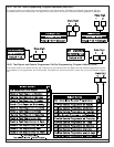
11.2 Installation Considerations
• Failure to install and program the control in accordance with the
requirements in this section voids the listing mark of Underwriters
Laboratories, Inc.
• The maximum standby battery capacity is 35 Ah @ 12 VDC.
• The total nominal standby current must not exceed 1.5 A nor 2.5
A when in alarm.
• The control must be mounted indoors and within the protected
area.
• Enclosure tamper switches (if used) must be connected to a 24-
hour zone.
• Grounding must be in accordance with article 250 of the NEC
(NFPA 70).
• At least one UL Listed keypad with zone display must be
connected.
• Zones must be connected to UL Listed, compatible devices.
• 50 Hz. AC input cannot be used in UL Listed Requirements.
• The ground wire provided with the enclosure must be connected
to the “Earth GND” connection on the control and the enclosure
tab.
• The keypad panic alarm output must follow the corresponding
zone function’s programming (e.g. fire = pulsing [or steady if not
a combination], burglary = steady). In all cases, the special
emergency keys must be silent.
• The ground start feature shall not be programmed.
11.3 Programming the DS7400Xi
When used in UL Listed Requirements, the control must conform
to certain programming requirements. The following is a list of the
required program entries and required accessories for specific
UL Listed Requirements.
11.3.1Household Fire Alarm Using Digital Alarm
Communicator Transmitter With Local Bell
The control must be installed in accordance with NFPA 72.
Required Accessories:
• At least one Detection Systems, Inc. Model DS250 Series smoke
detector with an MB Series base, DS280 Series, MX280 Series,
or another Listed compatible smoke detector.
• At least one DS7480 Bell Supervision Module.
• One Wheelock 46T-G10-12 bell or 34T-12 horn (will provide
85db for UL985 and NFPA 72 requirements; other Listed
compatible devices with a voltage range of 10.2 to 14.0 V may be
used) is required and must be installed inside the protected
area.
• The standard control enclosure can be used.
• At least one DS7447/DS7447E or DS7445/DS7445i Keypad must
be used.
• Four-wire detectors must be used with Listed power supervision
devices. A compatible Listed 4-wire detector is the Detection
Systems, Inc. DS250 in an MB4W base. A compatible Listed
EOL relay is the Detection Systems, Inc. EOL200.
• All zones must be used with the EOL resistor (P/N 25899),
provided.
1. Report Programming:
• Fire Zone Report must be programmed.
• Low Battery Report (Program Address 3336) must be
programmed.
• AC Failure Report (Program Address 3338) must be
programmed.
2. Timer Programming:
• Bell Cutoff Times (Program Addresses 4032 and 4033) must
be programmed for not less than 4 minutes.
3.Zone Function Programming:
• For household fire installations only, the output signal may be
pulsed or steady. For a combination system, see the selection
below on alarm output programming.
4.Alarm Output Programming:
• Program Address 2734 must be programmed as: Data Digit 1=
6, Data Digit 2= 3.
5.General Control Programming:
• Program Address 2732 must be programmed as: Data Digit 1=
0, Data Digit 2= 0.
11.3.2Grade A Household Burglary Alarm Using Digital
Alarm Communicator Transmitter With Local
Bell
The control must be installed in accordance with UL Standard
UL1641.
Required Accessories:
• At least one Wheelock 46T-G10-12 bell or 34T-12 horn (other
Listed compatible devices with a voltage range of 10.2 to 14.0 V
may be used) is required for this application.
• The standard DS7400 enclosure can be used.
1.Report Programming:
• Burglar Zone Reports must be programmed for those zones
used.
• Low Battery Report (Program Address 3336) must be
programmed.
• AC Failure Report (Program Address 3338) must be
programmed.
2.Timer Programming:
• Bell Cutoff Times (Program Addresses 4032 and 4033) must
be programmed for not less than 4 minutes.
• Entry Delay Timer (Program Addresses 4028 and 4029) must
be programmed for not longer than 60 seconds.
• Exit Delay Timer (Program Address 4030) must be programmed
for not longer than 45 seconds.
3.General Control Programming:
• Program Address 0000, Data Digit 2 must be programmed for
NO Swinger Shunts (enter 0, 1, or 2).
• Program Address 2732 must be programmed as: Data Digit 1=
0, Data Digit 2= 0.
4.Alarm Output Programming:
• Program Address 2734 must be programmed as: Data Digit 1=
6, Data Digit 2= 3.
• Program Address 2737 must be programmed as: Data Digit 1=
8.
In a system that includes both fire alarm and burglar alarm
devices, the system must produce distinct sounds for fire
and burglar alarm conditions either by using different
indicating appliances or by using distinct cadences for
the same appliance.