


Page 78 P/N: F01U035325-01 Copyright © 2007 Bosch Security Systems, Inc. DS7400Xi (4+) Reference Guide
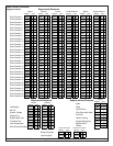
1. Report Programming:
• Burglar Zone Reports must be programmed for those zones
used.
• Fire Zone Reports must be programmed for those zones used.
• Low Battery Report (Program Address 3336) must be
programmed.
• AC Failure Report (Program Address 3338) must be
programmed.
3.General Control Programming:
• Must be programmed for no swinger shunts (Program Address
0000 data digit 2, enter 0, 1, or 2).
• Program Address 2732 must be programmed as: Data Digit
1=0, Data Digit 2= 0.
4.Commercial Fire Mode Programming:
• Local (Program Address 2733, data digit 1, enter as a 1 through
6).
• Central Station (Program Address 2733, data digit 1, enter as a
7 through *2).
• The keypad panic functions are not intended to be a substitute
for Listed manual pull boxes.
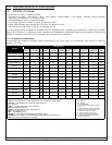
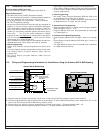
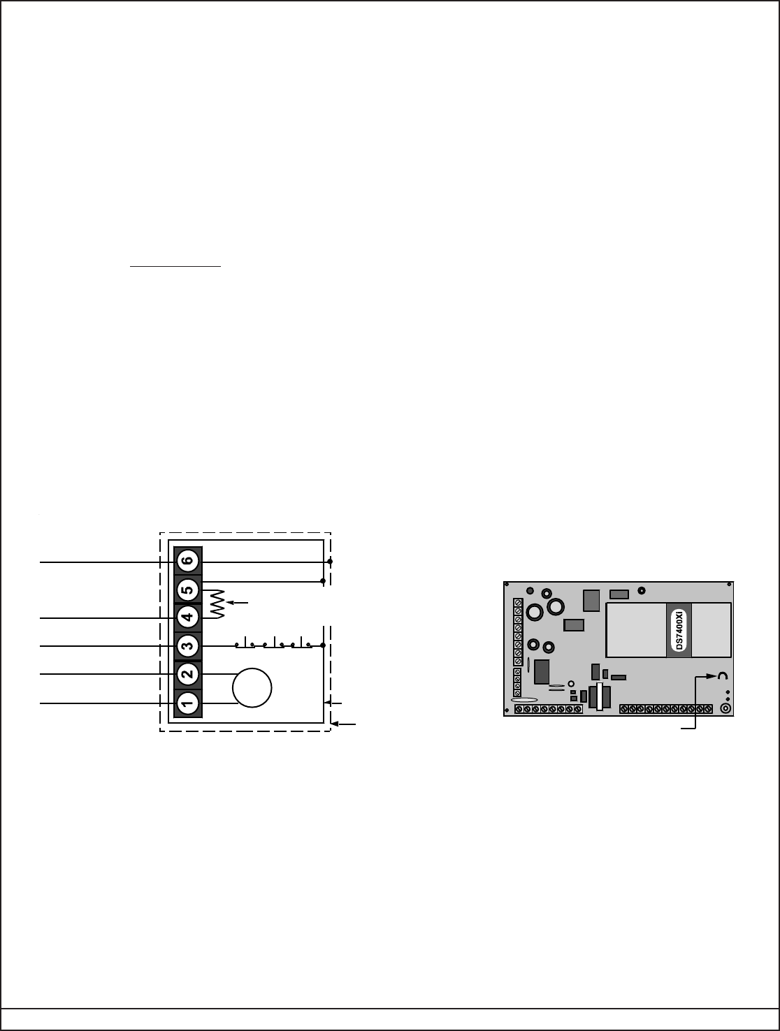
11.6 Wiring and Programming Information for Installations Using the Ademco AB-12 Bell/Housing
1) Disconnect the wire jumper from terminal 4 to the inner housing of the Bell Box (prevents a ground fault condition).
2) Connect wiring between the control and Bell Box as shown above. To use the AB-12 Bell/Housing, cut the jumper wire “JP1” on the
control. The EOL used in the AB-12 Bell/Housing must be 27 kΩ.
3) Program Zone 8 as a 24-hour zone by programming it to follow zone function 7. (Program address 0038 = 07).
4) Do not change the default programming of zone function 7. (Program address 0007 should be 22).
11.5 Commercial Fire Alarm
A.Central Station (DACT) and Local
The control must be installed in accordance with NFPA 72.
Required Accessories:
• DS7420i Dual Phone Line/Bell Supervision Module.
• For Local Commercial Fire Alarm: A Listed notification appliance
such as a Wheelock 46T-G10-12 bell or 34T-12 horn.
• If not using the phone line supervision, it must be disabled.
• AE-TR16 Transformer Housing.
• At least one DS7447/DS7447E must be used and assigned as
keypad 1. If only one is used, it may be connected to the keypad
bus if the keypad is mounted to the front of the box or within the
same room as the control equipment and the wire is run in
conduit (or equivalently protected against mechanical injury)
within 20 ft. (6.1 m) of the control equipment. If multiple
keypads are used,
one keypad only must be used on the options
bus and assigned as keypad 11-14 and meet the same
requirements as in single keypad use.
• 50 Hz. operation and ground start are automatically forced to the
disabled state when central station fire mode is selected.
Control/Communicator
Cut this jumper
JP1
T
o controlAlarm Output +
T
o controlAlarm Output –
To control Zone 8 Input
To control Loop Positive
To control Earth Ground
EOL
27 k
Ω
BELL
Bell Tampers
Outer Bell Box
Inner Bell Box Lining
Ademco AB-12 Bell/Housing
Terminal 1
Terminal 29 (+)
Terminal 30 (8-)
Terminal 5 (-)
Terminal 6 (A)
Alternate EOL (if not
using a Fire card)
Detection Systems’
P/N 28300
• Open Report (Program Address 3331) must be programmed.
• Close Report (Program Address 3332) must be programmed.
• 24-Hour Check-In Reports (Program Addresses 3340 and 3347)
must be programmed.
2.Timer Programming:
• Bell Cutoff Times (Program Addresses 4032 and 4033) must
be programmed for not less than 5 minutes.
• Entry, Exit Delay Times (Program Addresses 4028-4030) must
be programmed for not longer than 60 seconds.