


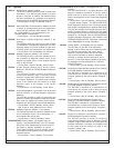
DS7400Xi ( 4+) Reference Guide Copyright © 2007 Bosch Security Systems, Inc. P/N: F01U035325-01 Page 5
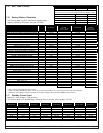
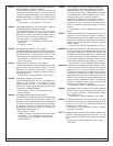
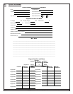
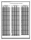
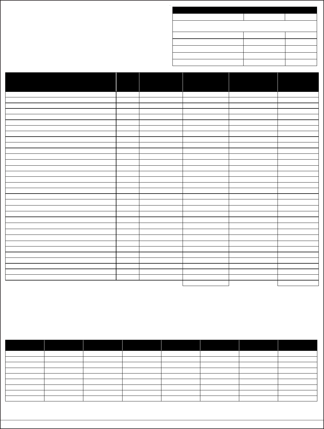
1.16 Backup Battery Calculation
• The following table is used to calculate the standby battery
capacity required by NFPA when using the DS7400Xi:
1.17 Standby Current Load
• Battery Ah - (20% Storage + 0.375 Ah Alarm)
• The following table is the derated battery divided by hours minus the control standby (175 mA):
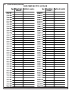
1.15 Max. Load Currents
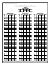
* = Add 15 mA for each additional zone in alarm.
** = When calculating Standby and Alarm Current for the Octal Relay Module, use 10 mA plus 40 mA for each activated relay.
*** = Maximum current draw if using the DS7400Xi Panel power supply. Total of all outputs cannot exceed 750 mA.
Rechargeable
Battery Size
Max. Standby
for 4 hours
Max. Standby
for 8 hours
Max. Standby
for 24 hours
Max. Standby
for 48 hours
Max. Standby
for 60 hours
Max. Standby
for 72 hours
Max. Standby
for 80 hours
7 Ah 1.0 A 470 mA X X X X X
8 Ah 1.2 A 580 mA X X X X X
14 Ah 1.5 A 1.1 A 270 mA X X X X
15 Ah 1.5 A 1.2 A 300 mA X X X X
17.2 Ah 1.5 A 1.5 A 380 mA 100 mA X X X
21 Ah 1.5 A 1.5 A 500 mA 160 mA 100 mA X X
28 Ah 1.5 A 1.5 A 740 mA 280 mA 190 mA 130 mA 100 mA
30 Ah 1.5 A 1.5 A 800 mA 310 mA 210 mA 150 mA 120 mA
35 Ah 1.5 A 1.5 A 970 mA 400 mA 280 mA 200 mA 170 mA
Device
Quantity
Standby Current
per Device
Total Standby
Current
(Quantity x Standby
Current per Device)
Alarm Current
per Device
Total Alarm
Current
(Quantity x Alarm
Current per Device)
DS7400Xi (4+) Control Panel 1 175 mA 175 mA 250 mA 250 mA
DS7416i Advanced Radio Communications Module 127 mA 127 mA
DS7412 - RS232 Serial Interface Module 35 mA max. 35 mA max.
DS7420i -Dual Phone Line/Bell Supervision Module 20 mA 140 mA
DS7430 – Multiplex Expansion Module 65 mA 65 mA
DS7432 – 8-Input Remote Module 10 mA 10 mA
DS7433 – 8-Input Direct Module 65 mA 80 mA*
DS7436 – Dual Multiplex Expansion Module 130 mA 130 mA
DS7445/DS7445i Keypad 75 mA 75 mA
DS7447/ DS7447E Keypad 100 mA 100 mA
DS7448 Keypad 80 mA 100 mA
DS7450, DS7452, DS7455 Contact Points
350
μ
A
350
μ
A
DS7457 – Single Zone Multiplex Input Module
350
μ
A
350
μ
A
DS7460 – Dual Zone Module 1 mA 1 mA
DS7465 – Input/Output Module 1 mA 1 mA
DS7480 – Bell Supervision Module 7 mA 50 mA
DS7481 – Single Phone Line Monitor 20 mA 20 mA
DS7488 – Octal Relay Module** 10 mA + 40 mA** 10 mA + 40 mA**
DS7489 – Solid State Output Module 10 mA 750 mA max.***
MX280 Series Multiplex Smoke Detectors
500
μ
A
560
μ
A
MX540 (DS7473) PIR Detector
800
μ
A
800
μ
A
MX835 TriTech
®
PIR/Microwave Detector 6 mA 35 mA
MX775 (DS7470) PIR Detector
200
μ
A
200
μ
A
MX794 (DS7474) PIR Detector
800
μ
A
800
μ
A
MX934 (DS7471) PIR Detector
200
μ
A
200
μ
A
MX938 (DS7472) PIR Detector
200
μ
A
200
μ
A
MX950 (DS7476) TriTech
®
PIR/Microwave Detector 6 mA 35 mA
RF3222 Wireless Receivers 30 mA 30 mA
2-Wire Smoke Detectors
4-Wire Smoke Detectors
Bells, Horns, etc.
Other Sensors
Other
Grand Total
Grand Total
Max. Load Currents Standby Alarm
UL Installations 1.5 A 2.5 A
Maximum Current By Output:
Not to exceed the maximum load currents listed above in Standby or Alarm
Aux. Power & Keypad (Combined) 1.0 A 1.0 A
Option Power 1.0 A 1.0 A
Bell Output X 1.75 A
Programmable Output 2 500 mA 500 mA
Loop Power + 500 mA 500 mA