


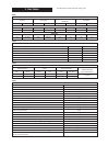

10.1 MAINS SUPPLY.
230 V ~, 50 Hz, 180 watts.
External Fuse: 3A. Internal Fuses: 2AT HRC(F1), and 1.AF (F2).
10.2 It must be possible to completely isolate the appliance.
10.3 The following connection alternatives must be used:
A 3 amp fused three-pin plug and unswitched shuttered socket
outlet (both complying with the requirements of BS 1363) or a
double pole isolator with a contact separation of 3mm in all
poles and supplying the appliance and controls only.
10.4 The appliance must be earthed.
10.5 Mains Cable. 0.75mm
2
(24 x 0.20mm) to BS 6500 Table 16.
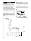
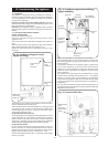
The mains cable must be connected into the terminal
X1,
marked
L (Brown or Red lead), N (Blue or Black lead) and the
earth stud and be held securely in the cable clamp. For access
undo the three bottom screws and remove the facia access cover.
See Fig. 7.
10.6 The wiring between the appliance and the electrical supply
shall comply with current IEE Wiring Regulations and any local
regulations which apply.
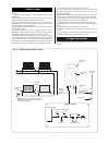
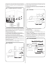
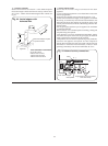
10.7 If a room thermostat and/or external programmer is to be
fitted refer to Figs 5 and 6. The devices must be suitable for use
with mains voltage.
10.8 A facia mounted mechanical programmer is available as an
optional extra. Instructions are supplied with the programmer kits.
10.9 A time switch or programmer can be fitted externally to the
appliance.
10.10 The boiler provides automatic frost protection, the use of
a frost thermostat is not recommended. However if an external
frost thermostat is considered necessary then it must be used in
conjunction with a programmer.
Important: To provide external frost protection the appliance
must have the Central Heating Temperature Control Knob set to
supply heating (the appliance may then be left with the central
heating turned off on the programmer).
Connection must be made at
X2 terminals RI and CL. For advice
on external frost thermostats contact Worcester Heat Systems
Technical Helpline
10.11 SAFETY CHECK.
After installation or in the event of an electrical fault the
electrical system shall be checked for short circuits, fuse failure,
incorrect polarity of connections, earth continuity and resistance
to earth.
10. Electrical
9
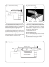
Fig. 7. Mains electricity connections.
Brown
Strain relief clamp
Blue
Brown
Green/yellow
Green/yellow
Programmer and room thermostat
strain relief clamps
230V
X1
X2
NL
Blue
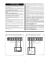
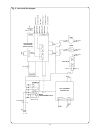
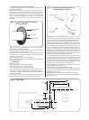
Fig. 8. Wiring diagram.
Safety
limit
stat
DHW
sensor
CH
sensor
Gas
valve
Pump
Main
Reg
Flow
switch
Air
pressure
switch
Spark
transformer
Mains in
2 pink
2 Blue
2 Red
2 Yellow
2 Orange
Brown
Blue
Blue
Brown
Blue
Brown
Brown
Blue
Link Link
X1
X2
X3
X6
X5 X4
Flame sense
electrode
Spark
electrode
Fan
Brown
White
Green
3 COM
1 NC
2 NO