


14.3 DISMANTLE THE APPLIANCE
To carry out a full and comprehensive service of the appliance
remove the following parts to gain access to the components
which need to be checked or serviced.
(a) Cabinet Front Panel. Remove by lifting off the supports.
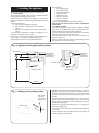
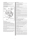
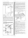
(b) Inner Casing Cover. Check that the electricity supply to the
appliance is turned off. Remove the cabinet front panel. Unscrew
the four screws securing the cover to the casing and lift off. See
Fig. 29.
(c) Facia Panel. Check that the electricity supply to the appliance
is turned off. Remove the cabinet front panel. Unscrew the two
upper screws as shown in Fig. 29. and hinge down the facia
taking care not to damage the pressure gauge capillary tube or
electrical connections.
(d) Bottom panel. Unclip and remove the appliance bottom
panel.
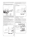
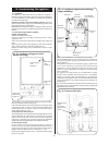
(e) Fan. Remove the inner casing cover. Carefully unplug the
electrical connections and pull off the sensing tubes. Unscrew
the four fixing screws and remove the fan assembly. See Fig. 30.
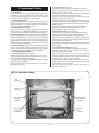
(f) Combustion Chamber Front. Remove the inner casing cover.
Undo the spring clips fixing the combustion chamber front. See
Fig. 30.
(g) Flue Hood Assembly. Remove the fan assembly. Remove the
combustion chamber front. Lift and slide the flue hood assembly
from the appliance. See Fig. 30. When refitting the hood ensure
that the rear return edge passes under the lip at the rear of the
combustion chamber.
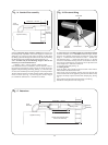
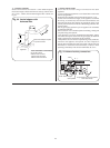
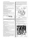
(h) Burner Assembly. Remove the combustion chamber front.
Pull off the two spark electrode leads and disconnect the flame
sense lead. Undo the burner fixing screws. Lift up and remove
the burner assembly from the appliance. See Fig. 31.
14.4 SERVICE OF COMPONENTS
Clean the Fan.
Any dust or fluff should be removed with a soft
brush or by blowing. Take care not to distort the pressure
sensing device.
Clean the Main Burner. Brush the blade tops and mixing tube
with a soft brush and check that all the flame ports are clear.
Remove any blockages with a non-metallic brush. Inspect the
injector and clean with a soft brush. Replace the injector if it
appears damaged. Do not use a wire brush or anything likely to
cause damage. Replace the spark and sense electrodes if they
appear damaged.
Clean the Gas to Water Heat Exchanger. Clean the heat
exchanger using a soft brush. Remove the deposits from the
bottom of the combustion chamber. Do not distort any of the
blades.
Combustion Chamber Insulation. Examine and replace any
pads that are damaged. Remove any dust or deposits using a
soft brush.
Reassemble the appliance in the reverse order.
Check that all components are in place and correctly fixed. Leave
the cabinet front panel to be fitted after checking the operation
of the appliance.
14.5 TEST THE APPLIANCE
On completion of the service and reassembly of the appliance,
check for gas soundness and the correct operation of the
appliance as described in Section 12 - Commissioning.
Refit the cabinet front panel and reset the controls to the users
requirements.
19
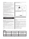
Fig. 31. Burner and electrode assembly.
Spark electrode
Injector
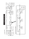
Fig. 30. Appliance components and fixings
(upper assembly).
Flue hood
Overheat
thermostat
Burner fixing
screws (2)
Combustion
chamber
cover fixing
clips (2)
Auto air
vent
Fan assembly
fixing screws (4)
Flue Gas
Test Point
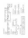
Fig. 29. Appliance casing and control
equipment fixings.
Inner casing
cover
screws (4)
Side casing
fixing
screws (4)
Facia panel
fixing
screws (2)
Bottom facia
panel fixing
screws (3)