


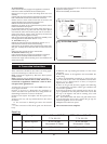

12.3 PROGRAMMER
Any programmer fitted on the appliance should be set up at this
stage following the instructions sent with the programmer.
12.4 APPLIANCE OPERATION
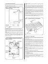
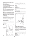
Turn off the gas and electricity supplies to the appliance.
Undo the two screws and hinge down the facia.
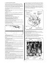
Loosen the burner pressure test point screw and connect a
pressure gauge. See Fig. 27.
Domestic Hot Water.
Set any Programmer to HEATING & WATER.
Turn on the gas and electricity supplies.
Set the Central Heating temperature control knob to Off.
A tap should be opened to create a hot water demand then a
continuous ignition spark will occur until the burner is alight and
sensed by the control circuit. The burner will light and remain at
its maximum setting. The burner pressure should be between
13.4 and 13.8 mbar on Natural gas (33.0 and 35.0 mbar on
Propane). If the burner pressure is low, check that the supply
pressure at the gas valve inlet is at least 19 mbar for Natural gas
(37 mbar for Propane).
Test for gas soundness at the joint between the burner and the
gas valve with leak detection fluid.
Note: The burner pressure is factory set and if (after checking
that the supply pressure is sufficient) the correct pressure is not
obtained then Worcester Heat Systems Service Department
should be contacted.
Gradually close the hot tap and check that the burner pressure
drops. Fully open the tap and check that the burner pressure
rises. Fully close the tap and check that the burner goes off. The
fan may continue running until the appliance has cooled.
Central Heating
Check that all the radiator valves are open.
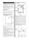
Check that the system is pressurised and set to the required
pressure as indicated on the gauge.
Set any Programmer to HEATING & WATER.
Turn on the gas and electricity supplies.
Set the room thermostat and the Central Heating Temperature
Control to maximum.
The burner will light.
The appliance will modulate its output between 7.5 and 23.4 kW
over a period of about twenty minutes.
Check the system to ensure that all the radiators are heating up
evenly.
Shut down all but one of the radiators and observe the burner
pressure fall. Open all of the radiator valves and check that the
burner pressure rises.
Balance the system so that the required temperature difference
across the central heating flow and return pipes is obtained. See
Table 3, Section 3 Data Tables.
Set the room thermostat to minimum and check that the burner
goes out. Reset the room thermostat to maximum and the
burner will re-light after a short anti-cycle delay and follow the
normal operating procedure.
Check for proper ignition of the burner after a break in the gas
supply. Turn off the gas service cock and wait for 60 seconds. The
burner will go out but sparking from the electrode will continue
for 10 seconds when the appliance will enter a “lockout” state.
Carefully open the gas service cock, interrupt the mains power
supply to the appliance for a few seconds to reset the controls
and observe the burner re-light and follow the normal sequence
of operation.
Turn off the gas service cock and the electrical supply to the
appliance.
Drain the system while the appliance is still hot.
Refill, vent and re-pressurise as described in Section 12.2.
Domestic Hot Water and Central Heating
Turn on the electricity supply to the appliance and open the gas
supply cock at the appliance.
Set the Central Heating temperature control knob to demand
and any programmer to HEATING & WATER. If a programmer is
fitted, set the domestic hot water to Continuous or 24 Hrs and
the central heating to ON. The burner will light and heat will pass
into the system. Turn on a hot water tap and check that after a
short delay fully heated hot water is discharged from the tap.
Close the tap and the burner will go off. After a short time the
appliance will then return to the central heating mode and
automatically balance with the system requirements.
Set the Central Heating Temperature Control Knob to OFF and the
burner will go out.
12.5 COMPLETION OF COMMISSIONING
Disconnect the pressure gauge and tighten the test point screw.
Restart the appliance and check for gas soundness around the
test point screw.
Refit the cabinet front panel.
If the appliance is being passed over to the user immediately,
refer to Section 13 - Instructions to the User and set the controls
to the users requirements.
If the appliance is to be left inoperative, check that the Central
Heating Temperature Control is set to OFF. Turn off the gas service
cock and switch off the electricity supply.
If there is any possibility of the appliance and system being left
inoperative during frosty conditions, drain the appliance and
system. If the premises are to be left unoccupied during frosty
conditions, then drain the appliance and system. For short
inoperative periods, leave the appliance under the control of the
built in frost thermostat or the remote frost thermostat (if fitted)
or leave operating continuously with the room thermostat set at
6°C.
17
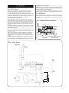
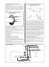
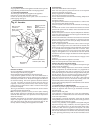
Fig. 27. Gas valve.
Main gas valve
connections
(Black : blue : brown :
green/yellow)
Burner pressure
test point
Inlet pressure test
point
Electrical connections Ð
modulator (Blue : Blue)
Modulating
solenoid
Minimum
pressure
adjuster
Maximum pressure
adjuster
Note: Clockwise to
increase and anti-
clockwise to
decrease the
pressure