


12.1 SUMMARY
The appliance is dispatched with the controls set to provide a
maximum output for domestic hot water and central heating of
23.4 kW (80,000 Btu/h). The appliance automatically modulates
to satisfy lower heat loads.
Domestic Hot Water and Central Heating Systems. Check that
both the mains water supply and central heating systems have
been fully flushed out at installation.
Gas Service. The complete system, including the meter, must be
inspected and tested for soundness and purged as indicated in
BS 6891.
12.2 APPLIANCE AND CENTRAL HEATING
SYSTEM PREPARATION
Remove the cabinet front panel.
Check that the electrical supply and the gas service to the
appliance are off.
Check that all the water connections throughout the system are
tight.
Open the system valves at the appliance. Open all the radiator
valves, fill the system and vent each radiator in turn.
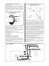
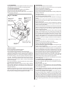
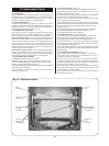
Remove the inner casing cover as described in section 14.3(b).
See Fig 24.
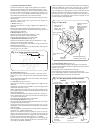
The automatic air vent will vent the appliance. Check that the air
vent cap has been removed. See Fig. 25.
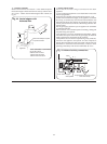
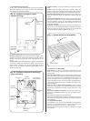
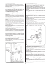
Check that the pressure relief valve operates by turning the knob
anti-clockwise until it releases. Water should be expelled from
the discharge pipe. See Fig. 26. Lower the control box to gain
access. Refer to Section 14.3(c).
Set the Expansion Vessel Pressure
The charge pressure of the expansion vessel as dispatched is 0.5 bar,
which is equivalent to a static head of 5 metres (17ft). The charge
pressure must not be less than the static head at the point of
connection. A Schraider type tyre valve is fitted to the expansion
vessel to allow the charge pressure to be increased if necessary.
Set the System Pressure
Fill the system until the pressure gauge shows 2.5 bar (37
lb/ins
2
) and check for water soundness. Release water from the
system using the relief valve test knob until the initial System
Design Pressure is obtained, up to a maximum of 1.5 bar.
Initial System Design Pressure (bar) = Expansion Vessel Charge
Pressure +0.3 (bar).
Note: 1 bar is equivalent to 10.2 metres (33.5 ft) of water.
Set the movable pointer on the pressure gauge to coincide with
the indicating pointer giving a permanent record of the set
system pressure.
If the pressure indicated on the pressure gauge is greater than
2.6 bar when operating at the maximum central heating
temperature, an extra expansion vessel must be fitted to the
system as close as possible to the appliance central heating
return connection.
The appliance (as dispatched) can accommodate a system
volume of about 100 litres. Refer to BS 7074 Part 1. If the system
volume is in excess of that accommodated by the expansion
vessel fitted to the appliance then an extra vessel must be fitted
as close as possible to the central heating return connection of
the appliance.
Any extra vessel fitted must be pressurised to the same figure as
the integral vessel. If the expansion vessel fails then the specified
replacement must be fitted.
12. Commissioning The Appliance
16
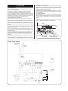
Fig. 25. Appliance components and fixings
(upper assembly).
Flue hood
Overheat
thermostat
Burner fixing
screws (2)
Combustion
chamber
cover fixing
clips (2)
Auto air
vent
Fan assembly
fixing screws (4)
Flue Gas
Test Point
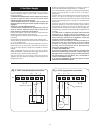
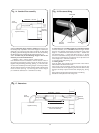
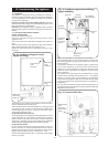
Fig. 24. Appliance casing and control
equipment fixings.
Inner casing
cover
screws (4)
Side casing
fixing
screws (4)
Facia panel
fixing
screws (2)
Bottom facia
panel fixing
screws (3)
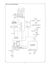
Fig. 26. Pressure relief valve.
Pressure relief
valve.
(Turn knob
anti-clockwise
to test).