


13. Domestic Hot Water Sensor.
Check that the electricity supply to the appliance is turned off.
Hinge the facia assembly in the servicing position as described in
Section 14.3(c and d).
Carefully pull off the two leads from the sensor.
Undo and remove the clamping screw.
Pull off the sensor and spring retaining clip from the pipe.
Fit the replacement sensor in the reverse order ensuring a layer
of heat sink compound is between the faces. Refit the leads.
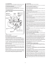
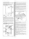
14. Circulating Pump. See Figs. 32 and 34.
Check that the electricity supply to the appliance is turned off.
Drain the central heating circuit as described in Section 15.3(a).
Hinge the facia assembly in the servicing position as described in
Section 14.3(c).
Undo the two union nuts and the pipe to the expansion vessel,
remove the pump from the pipe-work. Support the pump and
remove the electrical cover.
Disconnect the electrical wires taking note of their positions.
Fit the replacement pump in the reverse order using new sealing
washers.
(Alternatively replace the pump head only by removing the four
Allen screws on the pump, remove the head and support whilst
removing the electrical connections. Refit the new head).
Open the valves and fill and re-pressurise the system as
described in Section 12.2
Note: The direction of flow should be upwards. The speed should
always be set to maximum.
15. Expansion Vessel.
Drain the central heating circuit as described in Section 15.3(a).
Isolate the gas supply at the mains.
Then either fit a separate expansion vessel on the central heating
return to the appliance or replace the existing vessel as
described below.
Drain the domestic circuit as described in Section 15.3(b).
Disconnect the flue system at the boiler.
Disconnect the appliance pipework at the appliance entry points
ensuring precautions are taken to cope with any water
remaining in the appliance.
Remove the appliance from the wall.
Disconnect the expansion vessel from the appliance by undoing
the fitting nut at it’s base.
Fit the replacement vessel in the reverse order.
Open the valves and fill and re-pressurise the system as
described in Section 12.2
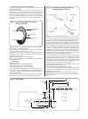
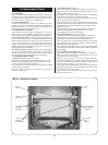
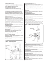
16. Pressure Relief Valve. See Fig. 35.
Drain the central heating circuit as described in Section 15.3(a).
Hinge down the facia assembly as described in Section 14.3(c)
Remove the Bottom panel as described in Section 14.3(d)
Undo the discharge pipe connection and remove the valve
retaining clip. Remove the valve taking care not to distort the
pipework.
Fit the replacement valve in reverse order. Reconnect the
discharge pipe.
Open the valves and fill and re-pressurise the system as
described in Section 12.2
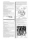
17. Water Flow Switch. See Fig. 36.
Check that the electricity supply to the appliance is turned off.
Drain the domestic hot water circuit as described in Section
15.3(b).
Remove the two upper screws and hinge down the facia panel as
described in Section 14.3(c).
Undo the two union nuts securing the “T” piece and remove the
housing from the pipework.
Disconnect the electrical connection.
Fit the replacement water flow switch in the reverse order
ensuring new fibre washers are fitted to the new switch body.
18. Domestic Hot Water Flow Restrictor. See Fig. 36.
Remove the water flow switch as described in Section 15.4-17.
Undo the two union nuts securing the “T” piece and remove the
housing from the pipework.
The plastic flow restrictor is located within the “T” piece on the
water flow switch.
Fit the replacement flow restrictor and reassemble in the reverse
order ensuring the fibre washers are in place.
19. Pressure Gauge.
Check that the electricity supply to the appliance is turned off.
Drain the central heating circuit as described in Section 15.3(a).
Remove the two upper screws and hinge down the facia panel as
described in Section 14.3(c).
Prize back the retaining clips securing the gauge to the facia
panel remove wire clip and unplug the gauge from the pump
inlet pipe.
Fit the replacement gauge in the reverse order ensuring the “O”
ring is in place.
Open the valves and fill and re-pressurise the system as
described in Section 12.2
22
Fig. 35. Pressure relief valve.
Pressure relief
valve.
(Turn knob
anti-clockwise
to test).
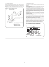
Fig. 36. Water Flow Switch. (Side View)
Flow Restrictor
Water Flow Switch
ÒTÓ Piece