


Technical Helpline.
The appliance is only suitable for fitting to a sealed system.
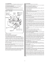
11.1 FLUE OPTIONS.
The standard flue length is from 127mm to 350mm measured
from the appliance casing to the outer wall.
Extension flue kits, a vertical take-off adapter, 45° and 90° flue
bends are available to increase the length and redirect the flue as
follows.
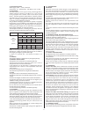
Horizontal balanced flue:
a) From 127mm to 2500mm straight flue.
b) From 127mm to 1750mm when a 90° flue bend is
required.
c) From 127mm to 1000mm when two 90° flue bends are
required.
A 90° flue bend is equivalent to 750mm of straight flue. A 45°
flue bend is equivalent to half a 90° bend.
Refer to Figs. 21 and 22 to determine whether extension kits,
90° flue bend, 45° flue bend, or adapters are required.
The maximum number of 90° flue bends allowed is two.
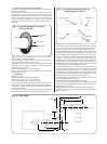
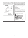
Flue components
1. Turret clamping ring.
2. Flue turret assembly
3. Flue terminal assembly
4. Extension air duct
5. Extension flue duct
6. In-line 90° flue bend
7. In-line 45° flue bend
8. Vertical flue adapter
The flue must be installed as specified in BS 5440 Part 1.
NOTE: READ THIS SECTION FULLY BEFORE COMMENCING
INSTALLATION
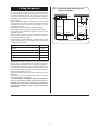
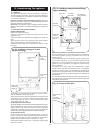
11.2 GENERAL FITTING.
Check that the appliance carton contains:- Appliance, Installers
Instruction Pack, Appliance Wall Plate, Users Information Pack,
Installer Hardware Pack and an appliance template.
Check that the position chosen for the appliance is in accordance
with the instructions given in Sections 4 and 5.
Hold the template to the wall. Check that the template is
horizontal. See Fig. 10.
Mark the position of the fixing holes and the position of the flue
hole centre line onto the wall. See Fig. 10.
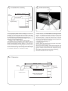
Side Flue – Extend the flue hole centre line from Fig. 11 along the
appropriate wall. Check that it remains horizontal and mark a
horizontal line. Measure 222mm from the junction of the walls
and mark a vertical line which will then give the position of the
flue hole.
Drill the two fixing holes 60mm deep for No. 12 size plugs. Cut
the flue duct hole at 110mm diameter (150mm dia. for internal
fitting). Ensure that the hole is horizontal through the wall. Fit
the wall mounting bracket.
Drill the two fixing holes 60mm deep for No. 12 size plugs. For
the boiler retaining screws.
Fix the wall plate and check that it is horizontal before tightening
the 2 screws.
Hang the appliance on the wall plate and screw the appliance to
the wall using the screws provided.
11. Installing The Appliance
11
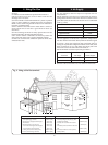
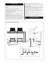
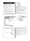
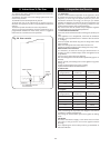
Fig. 10. Appliance mounting plate and flue position.
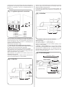
Fig. 11. Marking out the side flue position.
Mounting wall
Rear flue hole
110mm dia.
(150mm dia. for
internal fixing)
Side flue hole
110mm dia.
(150mm dia. for
internal fixing)
Appliance
casing
Mounting
plate
Fixing holes
(alternatives)
Mounting wall
Mounting
plate
222mm
Side wall
166mm
740mm
400mm
Rear flue position Side flue position
60mm
Appliance
casing
Rear flue hole
110mm dia.
(150mm dia. for
internal fixing)
Mounting wall
Side wall
222mm
166mm