


1.1 Gas Safety (Installation and Use) Regulations, October 1994
all gas appliances must be installed by a competent person in
accordance with the above regulations. Failure to install
appliances correctly could lead to prosecution.
1.2 The manufacturers notes must not be taken, in any way, as
overriding statutory obligations.
1.3 The compliance with a British Standard does not, of itself,
confer immunity from legal obligations. In particular the
installation of this appliance must be in accordance with the
relevant requirements of the following;
Gas Safety (Installation and Use) Regulations 1994 as amended.
Current IEE Wiring Regulations BS 7671.
Local Building Regulations.
Building Standards (Scotland)(Consolidation).
Bylaws of the local Water Company.
Health and Safety Document No. 635 (Electricity at Work
Regulations).
The British Gas Material and Installation Specification for central
heating and hot water
It should be in accordance with the relevant recommendations of
the following British Standards.
BS6798:1987 Specification for installation of gas fired hot water
boilers of rated input not exceeding 60 kW.
BS5449:1990 Central Heating for Domestic Premises.
BS5546:1990 Installation of gas hot water supplies for domestic
purposes.
BS5440:1:1990 Flues and Ventilation for gas appliances of rated
input not exceeding 60 kW: Flues.
BS5440:2:1989 Flues and Ventilation for gas appliances of rated
input not exceeding 60kW: Air Supply.
BS6891:1988 Installation of low pressure gas pipework
installations up to 28mm (R1).
BS7593:1993 Central Heating system cleansing and flushing.
BS5482:PART 1 Domestic Butane and Propane gas burning
installations in permanent dwellings.
1.4 To ensure that the installation will perform to the highest
standards, the system and components should conform to any
other relevant British Standards in addition to those mentioned
in the instructions.
1.5 The appliance complies with the Essential Requirements of
the Gas Appliance Directive and other Directives currently
applicable.
1.6 This appliance contains no asbestos products.
There is no potential hazard due to the appliance being
electrically unsafe.
There are no substances used that are a potential hazard in
relation to the COSHH Regulations 1988.
1.7 The advice and instructions given in this document covers, as
far as possible, the foreseeable situations which may arise. Contact
Worcester Heat Systems Technical Helpline for advice on specific
installations.
2.1 This appliance is not suitable for external installation.
2.2 The appliance controls are set to provide a maximum output
of 23.4 kW for the domestic hot water and central heating load.
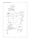
2.3 The control circuit provides direct burner ignition. A pilot is
not used.
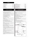
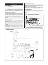
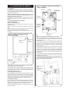
2.4 PRINCIPAL APPLIANCE COMPONENTS.
See Fig. 1.
A low thermal capacity Gas to Water heat exchanger
incorporating an integral Hot Water heat exchanger to provide
domestic hot water.
Fully modulating controls in the central heating and domestic
hot water modes of operation.
An expansion vessel, pressure gauge and pressure relief valve.
A fixed by-pass for the central heating system.
A Temperature safety cut-out control.
A water flow regulator.
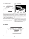
A standard telescopic horizontal flue assembly giving flue
lengths from 127mm to 350mm.
Optional extra extension flue kits to provide for flue lengths up to
2500mm.
An optional vertical flue kit to provide for flue lengths up to
3000mm including vertical flue terminal.
Optional facia mounted mechanical programmer.
2. General Information1. Installation Regulations
2
1. Installation Requirements . . . . . . . . . . . . . . . . . . . . . . . . . Page 2 10. Electrical. . . . . . . . . . . . . . . . . . . . . . . . . . . . . . . . . . . . . . . Page 9
2. General Information . . . . . . . . . . . . . . . . . . . . . . . . . . . . . . Page 2 11. Installing the Appliance . . . . . . . . . . . . . . . . . . . . . . . . . . Page 11
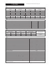
3. Data Tables . . . . . . . . . . . . . . . . . . . . . . . . . . . . . . . . . . . . . . Page 4 12. Commissioning the Appliance . . . . . . . . . . . . . . . . . . . . Page 16
4. Siting the Appliance . . . . . . . . . . . . . . . . . . . . . . . . . . . . . . Page 5 13. Instructions to the User . . . . . . . . . . . . . . . . . . . . . . . . . . Page 18
5. Siting the Flue. . . . . . . . . . . . . . . . . . . . . . . . . . . . . . . . . . . . Page 6 14. Inspection and Service. . . . . . . . . . . . . . . . . . . . . . . . . . . Page 18
6. Air Supply. . . . . . . . . . . . . . . . . . . . . . . . . . . . . . . . . . . . . . . Page 6 15. Replacement of Parts . . . . . . . . . . . . . . . . . . . . . . . . . . . . Page 20
7. Sealed System . . . . . . . . . . . . . . . . . . . . . . . . . . . . . . . . . . . Page 7 16. Conversion Instructions. . . . . . . . . . . . . . . . . . . . . . . . . . Page 23
8. Open Vent System. . . . . . . . . . . . . . . . . . . . . . . . . . . . . . . . Page 7 17. Operational Flow Diagrams. . . . . . . . . . . . . . . . . . . . . . . Page 24
9. Hot Water Supply . . . . . . . . . . . . . . . . . . . . . . . . . . . . . . . . Page 8 18. Fault Finding . . . . . . . . . . . . . . . . . . . . . . . . . . . . . . . . . . . Page 26
. . . . . . . . . . . . . . . . . . . . . . . . . . . . . . . . . . . . . . . . . . . . . . . . . . . . . . . . . 19. Component Parts List. . . . . . . . . . . . . . . . . . . . . . . . . . . . Page 34
Contents
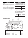
Fig. 1. Water flow diagram.
Bi-thermal
gas to water
heat
exchanger
Automatic
air vent
Domestic
water flow
switch
Pressure
relief valve
Safety
discharge
Domestic
hot water
out
Domestic
cold
supply
C.H.
return
Sealed
system
expansion
vessel
Circulating
pump
Fixed
by-pass
C.H.
flow