


15.1 IMPORTANT
Switch off the electricity and gas supplies before replacing any
components. After the replacement of any components, check
for gas soundness where relevant and carry out functional
checks as described in Section 12 - Commissioning
15.2 COMPONENT ACCESS
To replace components it is necessary to remove one or more
sections of the cabinet and cover plates within the appliance as
described in Section 14.3. The facia panel may also need to be
hinged down as described in Section 14.3 (c).
15.3 DRAINING THE APPLIANCE
Check that the electricity supply to the appliance is turned off.
Before removing any component holding water it is important
that as much water as possible is removed from the appliance.
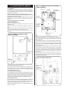
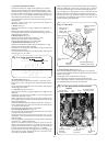
(a) Central Heating Circuit. Turn off the central heating flow and
return valves at the appliance. Open the pressure relief valve,
make sure that the dust cap on the auto air vent is removed. See
Fig. 30. Close the pressure relief valve when the flow has
stopped. Some water will remain in the expansion vessel, pump
and Gas to Water heat exchangers and extra care must be taken
when removing these components.
(b) Domestic Hot Water Circuit. Turn off the mains cold supply
valve at the appliance and open the lowest hot water tap. A
quantity of water will remain in the Gas to Water heat exchanger,
extra care must be taken when removing this component.
15.4 COMPONENT REPLACEMENT
1. Automatic Air Vent.
See Figs. 30. and 32.
Remove the inner casing cover as described in Section 14.3 (b).
Drain the central heating circuit as described in Section 15.3 (a).
Unscrew air vent from the heat exchanger.
Fit the replacement assembly ensuring thread sealant is applied
and the dust cap is removed.
Open the valves and fill and re-pressurise the system as
described in Section 12.2.
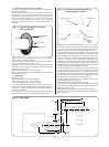
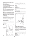
2. Air Pressure Switch. See Fig. 34.
Check that the electricity supply to the appliance is turned off.
Remove the cabinet front panel as described in Section 14.3 (a)
and lower the facia. Section 14.3(c).
Carefully pull off the sensing tubes and the electrical connections
from the switch. Remember to note their positions.
Unscrew the two screws behind the Air Pressure Switch and
remove the switch from the appliance.
Fit the replacement switch in the reverse order ensuring that the
electrical connections have been made to the correct terminals
on the switch. Check that the sensing tubes are fitted correctly.
3. Fan. See Fig. 30.
Check that the electricity supply to the appliance is turned off.
Remove the fan assembly as described in Section 14.3(e).
Fit the replacement fan in the reverse order.
4. Overheat Thermostat. See Fig. 30 and 32.
Check that the electricity supply to the appliance is turned off.
Remove the inner casing cover as described in Section 14.3 (b).
Carefully pull off the two wires from the thermostat head.
Undo the retaining nut on the top of the appliance and remove
the retaining clip from the heat exchanger. Carefully withdraw
the thermostat from the appliance.
Fit the replacement thermostat in the reverse order ensuring that
some heat sink compound is between the thermostat and the
heat exchanger.
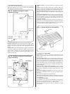
5. Gas to Water Heat Exchanger. See Fig. 32.
Check that the electricity supply to the appliance is turned off.
Drain the central heating circuit and domestic circuits as
described in Section 15.3 (a) and (b).
Remove the inner casing cover, fan, flue hood assembly,
combustion chamber front, overheat thermostat, automatic air
vent and combustion chamber side insulation as described in
Sections 14.3 (b, e, f and g), 15.4 (1) and 15.4 (4).
Fit the replacement heat exchanger in the reverse order ensuring
that all the fibre washers are correctly fitted and a layer of heat
sink compound is on the thermostat.
Open the valves and fill and re-pressurise the system as
described in Section 12.2.
15. Replacement Of Parts
20
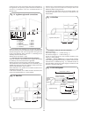
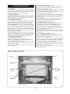
Fig. 32. Combustion chamber.
Heat
exchanger
Overheat
Thermostat
Hot water heat
exchanger
connections
Cut-outs in
combustion
chamber sides
Pump bulk
head
connector
Central heating
heat exchanger
connections
Auto air
vent