


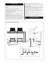
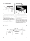
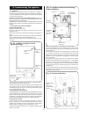
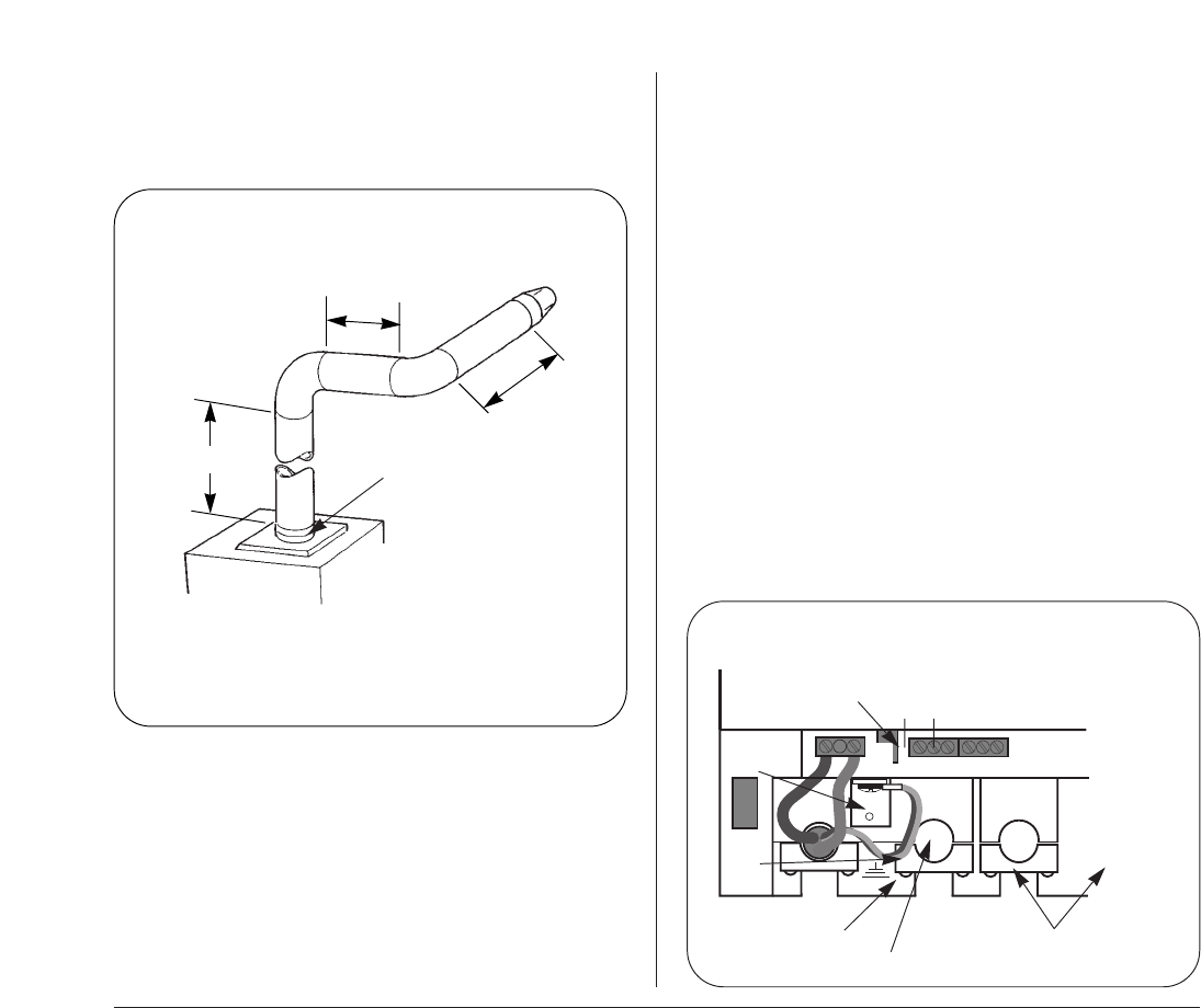
11.7 VERTICAL ADAPTER
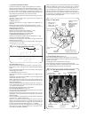
Measure and fit the flue as in Section 11.6 Flue bends except the
first section length is measured from the case top and the ducts
are cut to
X – 168mm. The minimum length for X is 190mm. See
Fig. 22.
11.8 FINAL INSTALLATION
Check that all the water and gas connections have been
tightened.
If a facia mounted programmer is to be fitted follow instructions
with the programmer..
Remove the facia bottom panel as described in Section 14.3(c).
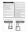
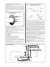
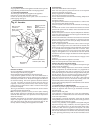
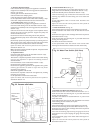
Connect the mains electrical supply to the appliance at terminal
X1. See Fig. 23. Connect any room and/or frost thermostats. The
electrical leads must pass through the appropriate space in the
control panel and be fixed with the cable clamps provided. Refit
the facia panel.
Test the gas supply pipework up to the appliance for soundness
as indicated in BS 6891.
Refer to Section 12 for a full description of the filling, venting and
the pressurising of the system.
If the appliance is not to be commissioned immediately, replace
the cabinet front panel. Check that the gas supply, the electrical
supply and the water connections are all turned off.
If the premises are to be left unoccupied during frosty conditions,
then drain the appliance and system. For short inoperative
periods, leave the appliance under the control of the built in frost
thermostat or the remote frost thermostat (if fitted) or leave
operating continuously with the room thermostat set at 6°C.
15
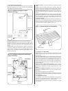
Fig. 22. Vertical adaptor with
horizontal flue.
X-168
Y-162
90¡
90¡
Appliance
Vertical flue adaptor required
for upwards section
TOTAL STRAIGHT FLUE LENGTH
X + Y + Z or X + Z
2500mm with one bend
1750mm with two bends
1000mm with three bends
Z-41
Fig. 23. Mains electricity connections.
Brown
Strain relief clamp
Green/yellow
Programmer and room thermostat
strain relief clamps
230V
X1
X2
NL
Blue