


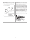
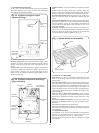
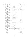
20. Control Board.
Check that the electricity supply to the appliance is turned off.
Undo the 3 screws and remove the facia bottom panel.
Remove the two upper screws and hinge down the facia
assembly.
Carefully pull off all the connectors. Disconnect the mains supply
lead at terminal
X1 and the earth connection at the back.
Remove the four corner screws on the back of the facia and
separate the metal back panel from the plastic facia.
Remove and retain the brass nut and washer.
Release the six pillars on the control board and pull the control
board forward off the back panel.
Fit the replacement board in the reverse order ensuring it is
pushed firmly onto the six pillars and clicks into place. Special
care should be taken with the brass post and nut to ensure a
good earth contact. (Check earth continuity between the
incoming earth and the appliance chassis).
Refit the facia panel and hinge the control box assembly in the
servicing position as described in Section 14.3 (c).
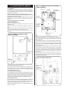
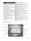
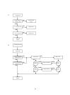
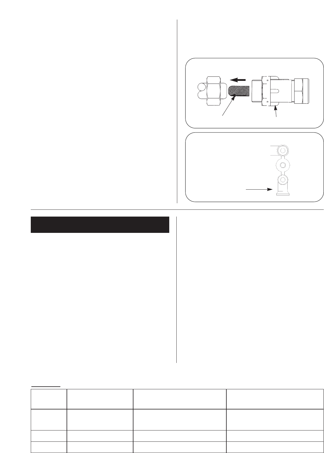
21. Gauze filter. See Fig. 37.
Remove the water flow switch as described in section 15.4-17.
Undo the lower union nut on flow switch housing.
Undo the nut on the isolating valve and remove the mains water
inlet pipe. Carefully extract the filter from the valve end of the
pipe.
Replace the filter and refit the pipe in reverse order.
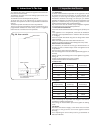
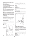
22. Flue flow sensor. See Fig. 38.
Check that the electricity supply to the appliance is turned off.
Remove the fan assembly as described in Section 14.3(e).
Unscrew the single central retaining screw and withdraw the
sensor from the fan.
Fit the new sensor ensuring the correct orientation and carefully
tighten the retaining screw.
Refit the fan assembly in reverse order.
23
Fig. 37. Gauze Filter.
Gauze Filter
Positive
Isolating Valve
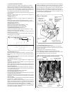
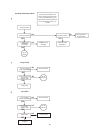
These instructions should be used when converting appli-
ances from natural gas to LPG and vice versa.
Only components supplied by Worcester Heat Systems
should be used.
Only competent persons should attempt the conversion.
Conversion from Natural Gas to LPG should not be
carried out on appliances installed in a room or inter-
nal space below ground level.
1.
Ensure the gas service cock is turned OFF and the elec-
trical supply is isolated.
2. Refer to section 14.3 Dismantle the Appliance to
remove the boiler front panel and inner casing. Follow the
dismantling instructions to remove the burner.
3. Remove the injector and replace with the injector from
the kit.
4. Remove the nut, end cap and bracket from the end of
the burner.
4.1 For conversion to Natural gas remove the internal
gauze.
4.2 For conversion to LPG fit the gauze into the burner
body.
5. Refit the end cap ensuring the bracket is in the correct
orientation.
6. Refit the burner to the appliance and re-assemble the
inner casing.
7. Follow the dismantling instructions to remove the gas
valve and refit the new valve. See Installation Instructions:
Section 15.4.11 Replacement of Parts, Component
Replacement, Gas Valve.
8. Turn on the gas and electricity supplies and following
the commissioning procedure confirm gas soundness and
correct boiler operation.
9. Set the gas pressure to the required rate for the new gas
type as specified on the data plate. When this is done refit
the cap to the adjuster and seal its retaining screw with
paint or nail varnish.
10. Turn off the boiler and when cool peel off the arrow
from the data plate and re-stick it against the gas type for
which the appliance is now converted.
11.Replace the boiler front panel.
The conversion is now complete.
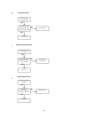
16. Conversion Instructions
Item No. Description Natural Gas to LPG Kit LPG to Natural Gas Kit
7 716 192 131 7 716 192 132
1. Burner Injector 8 716 140 209 8 716 140 224
Stereomatic 2.78mm Stereomatic 4.3mm
2. Burner Gauze 8 716 142 601 Remove Gauze
3. Gas Valve 8 716 142 430 8 716 142 413
Parts List
Fig. 38. Flue flow sensor.