


9
AquaSmart Boiler Control Manual
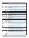
Test the Low Water Cut-off (LWCO) Safety Function
WARNING! Avoid touching or shorting the live
terminals during this test.
Turn electric power ON to energize AquaSmart control.
Perform the following tests to verify the LWCO function.
For AquaSmart 7600A: Remove the green sensor
lead from the ground screw. The sensor should cause
the AquaSmart display to indicate, “LOCKOUT – LOW
WATER”. If it does not, replace the sensor.
For AquaSmart 7600B:
Remove the green sensor
lead from the ground screw and remove both the B1 and
B2 (24 Vac) leads from their terminals. The sensor should
cause the AquaSmart display to indicate, “LOCKOUT –
LOW WATER”. If it does not, replace the sensor.
Attach wires and tighten terminal screws securely
when testing is complete.
•
•
•
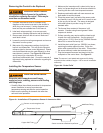
2-in-1 Installation Instructions
This is very important for successful control operation.
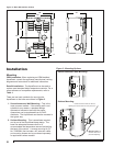
Remove the existing immersion well. Clean the
threads in the boiler port tapping. Follow all applicable
safety codes, rules and guidelines for removing/
installing immersion wells.
Apply pipe sealant to the 2-in-1 sensor threads and
install it securely into the port. BECKETT
RECOMMENDS ONLY TO USE TEFLON TAPE OR
RECTORSEAL NO. 5 PIPE SEALANT.
Tighten with 1-1/8” open end or box wrench. Pipe
wrenches, pliers, and adjustable wrenches will
damage/round-off the hex.
Securely install the AquaSmart control to the sensor.
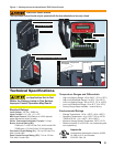
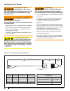
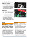
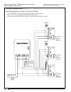
Plug the 2-in-1 Sensor RJ connector (phone jack style)
into the receptacle (Item a, Figure 6) on the control.
Route the 36” green wire through the AquaSmart
bottom rectangular slot (Item c, Figure 6). Securely
install the fork connector of the 36” ground wire and
the ground wire from the 2-in-1 sensor under the
ground screw at the bottom of the control (Item b,
Figure 6).
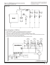
Thoroughly clean the pipe surface and securely
tighten the pipe clamp on the water inlet pipe to the
boiler as close to the boiler as possible.
Route the 36” green ground wire to the pipe clamp
then cut to proper length, if necessary.
Strip the wire and insert the stripped end into hole on
the pipe clamp (item d, Figure 7). Tighten retaining
screw against the wire making sure that you have
good contact.
Complete control wiring and fi ll the appliance with
water to the pressure required, according to appliance
manufacturer’s instructions. Make sure all air is
purged from the system and there are no leaks. Turn
on power to the appliance and observe one call for
heat cycle with shut off at set temperature.
1.
2.
3.
4.
5.
6.
7.
8.
9.
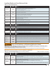
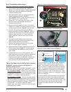
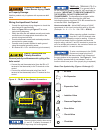
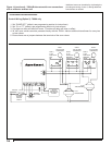
Figure 8 - Sensor Water Detection Method
Ground Screw
2-IN-1 SENSOR
AquaSmart
Boiler Control
Ground Wire
Pipe Clamp
Incomplete
Circuit
Water Not Present
Water Present
Complete
Circuit
Water Inlet
The AquaSmart 2-in-1 Sensor uses the “conduction”
method to detect whether water is present in the
boiler. This is done by using the water in the boiler
itself to “conduct” a signal and complete an electrical
circuit. It is necessary that the ground wire from the
sensor be bonded to the boiler wall (not the jacket -
unless the jacket is bonded to the boiler wall). When
water is not present, there is no “conduction” and the
circuit is incomplete.
For the AquaSmart we recommend that a grounding
pipe clamp be mounted to the water inlet pipe, and
that a ground wire be bonded from the pipe clamp to
the green terminal inside the AquaSmart control. The
2-in-1 sensor green “ground wire” shall also be
bonded to the green terminal in the AquaSmart
control.
Figure 6 - Sensor lead & ground screw connections
a
b
c
Figure 7 - Ground Clamp and Grounding Wire
d