


7
AquaSmart Boiler Control Manual
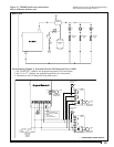
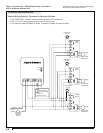
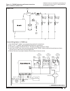
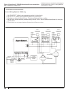
Compare the attached wires to available wiring
diagrams on the control cover and to the devices to
which they can be traced. If wiring diagrams have
been lost they are available later in this manual.
Label each wire accordingly, to ensure accurate
reconnection. (Masking tape works well for labeling.)
Remove each wire from the old control. Make sure
each label is intact.
Loosen the control mounting arrangement and remove
the control from the system.
Make note of the temperature settings for high limit,
low limit and differentials. This will provide important
reference data for the new control adjustment. Please
note that differentials may be used differently in other
manufacturer’s controls. See Figure 19 & 16 toward
end of manual for a description of how the
AquaSmart’s differentials work. Consult the manual of
the control being replaced for information regarding its
differentials.
1.
2.
3.
4.
5.
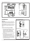
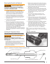
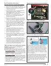
Installing the Temperature Sensor
Figure 4a - Installation of Temperature Sensor in Immersion Well
This is very important for successful control operation.
Temperature Sensor
Brass Fitting
Sensor must butt against end
Copper Well Tube
Sensor connects to Beckett AquaSmart
Removing the Control to be Replaced
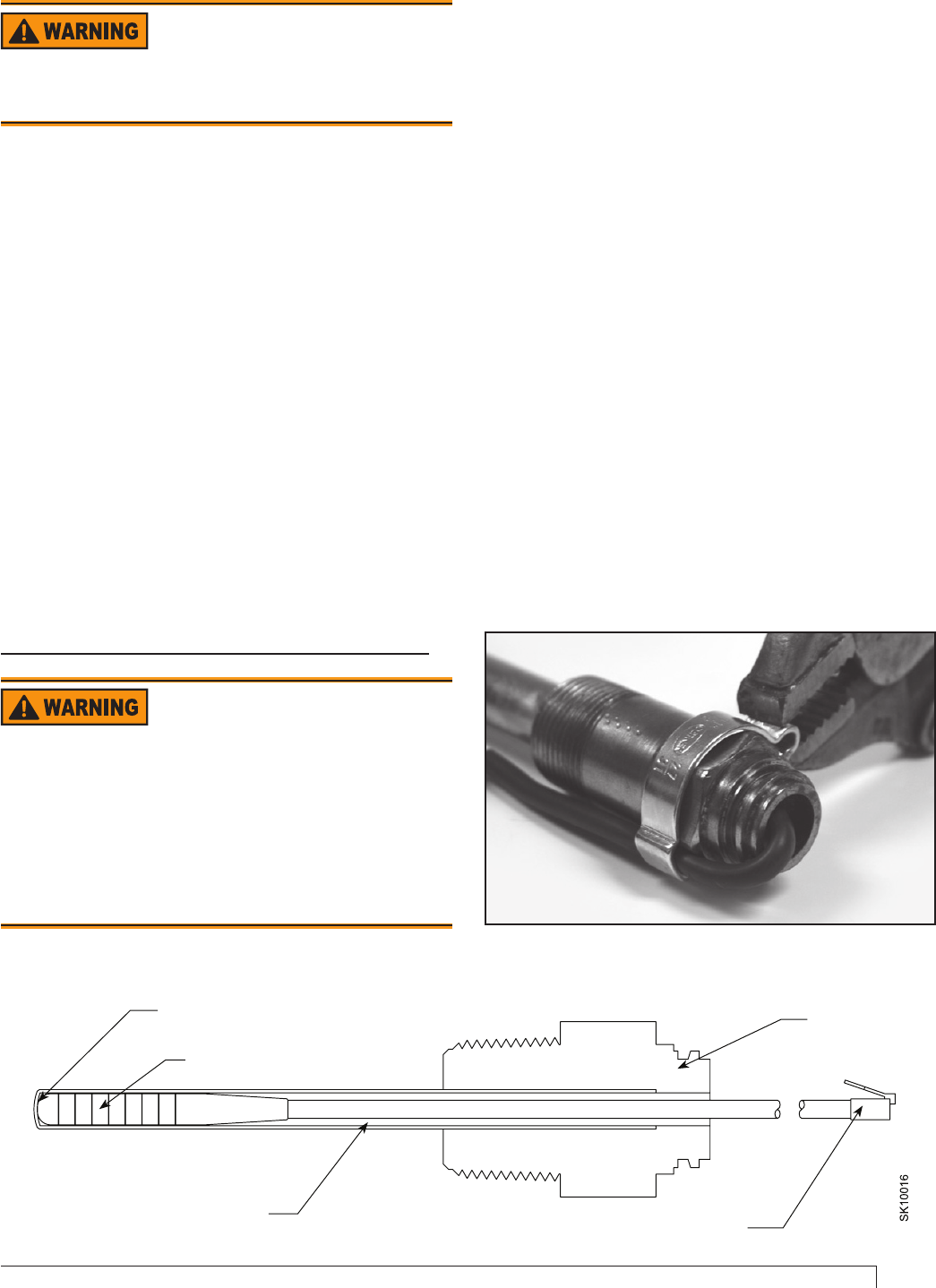
Figure 4b - Strain Relief
Electrical shock hazard.
Disconnect all electrical power to the appliance
circuit before replacing the control. There may be
more than one disconnect switch.
Burn and Scald Hazard
Excessive water temperatures could cause
explosion, burns, scalding, pressure relief fl ooding
and fi tting leaks.
Carefully follow the outlined procedures for temperature
sensor installation to ensure accurate water
temperature sensing and effective control operation.
Make sure the plumbing for domestic hot water has
anti-scald valve protection.
y
y
Make sure the immersion well is clean inside, has no
leaks, is of proper length and is otherwise suitable for
receiving the new control and temperature sensor.
Replace questionable wells with new ones and use
pipe sealant to seal the threads.
Grasp the sensor lead, just behind the sensor probe
and carefully insert it into the well until it comes to rest
at the very end of the well.
The sensor is designed
with radial splines to provide a snug fi t in most
standard wells.
The thermal time constant of the sensor is 40
seconds. Consider using thermal grease if faster
response in desired.
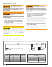
Surface mounting may require additional lead length
to reach the control receptacle. Use the extension
cable (part no. 52120), found in the 7600RMU Remote
Mount Kit, to extend the lead by 48”.
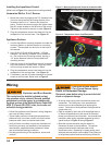
Install the strain relief (part no. 3266201) as shown,
capturing the cable against the hex. Crimp the
strain relief opposite side of the cable. This anchors
the sensor securely inside the immersion well.
Plug the temperature sensor lead terminal into the
receptacle on the control base. See Figure 10.
Note: The sensor is not tested and approved for being
mounted to the outside of a pipe. It is for use in immersion
wells only.
1.
2.
3.
4.
5.
6.
7.