


10
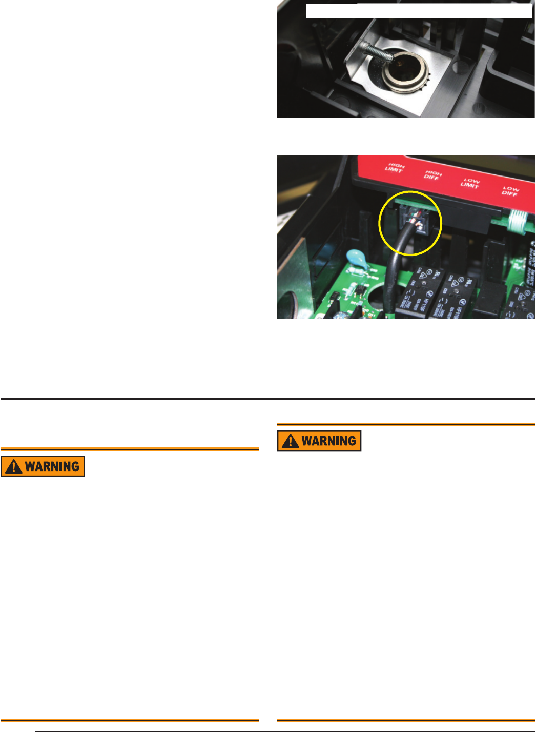
Immersion Well or 2-in-1 Sensor
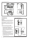
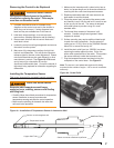
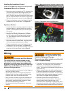
Mount the control by aligning the 7/8” diameter hole
(found on back) around the mating feature of the
immersion well or 2-in-1 sensor and press into
place. Position the control upright and tighten down
the #10 screw located on the left side of the control.
Tighten so that control is securely in place (Figure 9).
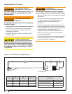
Plug the temperature sensor lead terminal into the
receptacle on the control base. See Figure 10.
Appliance Surface
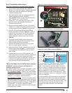
Use the AquaSmart mounting template to locate the
mounting holes in a desired location on mounting
surface. The template can be found in the back of
this manual.
Use (3) #8 x 3/4” self drilling screws (.110 hole
diameter if pre-drilling) included in the installation
kit. Run screws into mounting surface, leaving a
1/4” space between bottom of screw head and
mounting surface.
Open the cover of the AquaSmart control to expose
key hole locations in plastic case. Align key holes
over mounting screws and secure in place.
Plug the temperature sensor lead terminal into the
receptacle on the control base. See Figure 10.
If necessary, use the 48” cable extension to connect
sensor to control base. Refer back to Figure 3.
1.
2.
1.
2.
3.
4.
5.
Installing the AquaSmart Control
(Refer back to Figure 3 for appropriate mounting method)
.
Figure 9 - Mounting Clamp and Screw for Immersion Well
For clarity, the printed circuit board is not shown.
Figure 10 - Temperature Sensor Lead/Receptacle
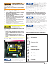
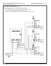
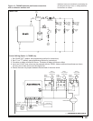
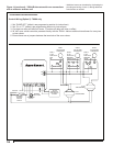
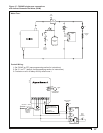
Wiring
Electrical Shock, Fire,
Explosion and Burn Hazards
This control must be installed, adjusted and put
into operation only by a trained, licensed, qualifi ed
professional or service agency in accordance with
the latest revision of the National Electric Code ANSI/
NFPA 70 (Canada CSA C22.1) state, local codes and
authorities having jurisdiction.
Follow the appliance manufacturer’s wiring diagrams
and note all safety controls.
Typical safety controls include high temperature or
pressure limits, low water cutoffs, anti-scald valves,
pressure relief valves and water feed valves.
Verify all limits and safety controls are installed and
functioning correctly, as specifi ed by the appliance
manufacturer, applicable safety standards, codes
and all authorities having jurisdiction.
Provide ground wiring to the appliance, burner and
controls.
y
y
y
y
Electrical Shock Hazard.
Can Cause Severe Injury,
Death, or Equipment Damage.
Disconnect power before wiring to prevent electrical
shock or equipment damage.
All wiring must comply with local electrical codes and
ordinances. The limits given in the specifi cations
section must not be exceeded when applying this
control. Terminals on the AquaSmart are approved for
copper wire only.
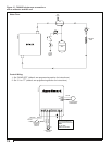
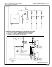
Refer to the label on the inside of the AquaSmart door or
to Technical Specifi cations in this manual for Electrical
ratings and maximum load information. Use manufacturer
instructions when wiring controlled equipment or refer to
typical hookups in Figure 12 through Figure 17.
More than one service switch may be needed to
disconnect all power to the AquaSmart. The optional
power disconnect switch interrupts power to the
AquaSmart control. Depending on system wiring, some
terminals and connections (most notably ZR and the input
to the optional power disconnect switch) may still be live.
y
y
y