33
AquaSmart Boiler Control Manual
During Annual Maintenance or More Frequent
Service Intervals, Verify the below items.
Note: The 7600 control has no serviceable internal
parts. DO NOT attempt to repair a malfunctioning
control.
The control is clean and all vents are free of dust, lint or
foreign material.
All wiring is tight, terminals are free from corrosion and
insulation is intact.
There is no physical damage to the case or display.
There is no evidence of water damage on the control or
terminals.
The control is securely mounted to the well or other
mounting support.
The sensor is in its place, with no evidence of tampering.
The sensor lead on remote mounted units is in good
condition and securely anchored in the immersion well
with the
strain relief.
The control temperatures, differentials and optional
functions are set correctly and working to established
specifi cations. Consult the service tag or label on the
boiler.
A record of service and any adjustments are made to the
service label or tag.
The control door is attached and securely closed.
□
□
□
□
□
□
□
□
□
□
Before Leaving the Installation Site, Verify:
All wiring has been done correctly in a workmanlike way,
is secure and meets all applicable codes.
AquaSmart control temperature settings, differentials and
optional functions are correctly set.
The control program is functioning properly by observing
at least one complete cycle.
At shutdown, the temperature and pressure level match
the recommended settings.
The pressure relief valve operation and boiler water feed
system works properly by bleeding some water and
observing the refi ll cycle.
The low water cutoff operation by lowering the water level
until it shuts the burner off.
The boiler passages and vent system are clear of
obstructions and operating to the appliance
manufacturer’s specifi cations and all required clearance
dimensions to combustible materials are met.
With combustion test instruments the burner is set to
manufacturer’s specifi cations.
After the system has run through a complete cycle, that
all fi ttings are free of leaks.
A record has been made of all service work and all
temperature control settings and optional functions.
Attach a label or tag to the boiler for future reference.
The AquaSmart Installation Manual is left at a suitable
location near the boiler for future reference and the
equipment owner is informed of this.
The control door is attached and securely closed.
□
□
□
□
□
□
□
□
□
□
□
□
ServiceFinal Checklist
Accessories
AquaSmart Remote Mount Unit Pack • 7600RMU
Includes:
Cable Assembly with Coupler
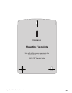
Mounting Template
Self-drilling Screws (Qty:3)
Cable Ty-wrap
AquaSmart Temperature Sensor Unit Pack • 7600TSU
Includes:
Temperature Sensor
Cable Ty-wrap
Joint Compound
Installation Instructions
AquaSmart 2-in-1 Sensor Unit Pack • 76002N1S01U
Includes:
2-in-1 Sensor
36” Ground Wire
Pipe Clamp for grounding
Installation Instructions
○
○
○
○
○
○
○
○
○
○
○
○


