


11
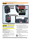
AquaSmart Boiler Control Manual
Explosion Hazard. Can
Cause Severe Injury, Death
or Property Damage.
Use this product only in systems with a pressure relief
valve.
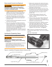
Wiring the AquaSmart Control
Consult the appliance wiring diagrams to check the
manufacturer’s specifi cations.
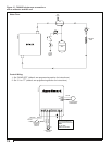
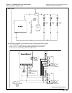
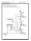
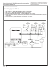
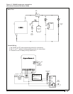
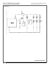
Refer to Figure 12 through Figure 17 for some
typical wiring diagrams.
Verify the wires are still labeled correctly and make
connections to the appropriate terminals on the
control wiring terminal strip.
Provide disconnect means and overload protection
as required on power supply.
Connect control conduit bracket to earth ground
using the supplied grounding screw.
B1 terminal is a 1/4 in. tab terminal (quick connect).
○
○
○
○
○
○
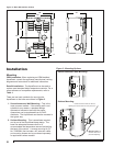
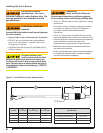
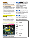
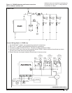
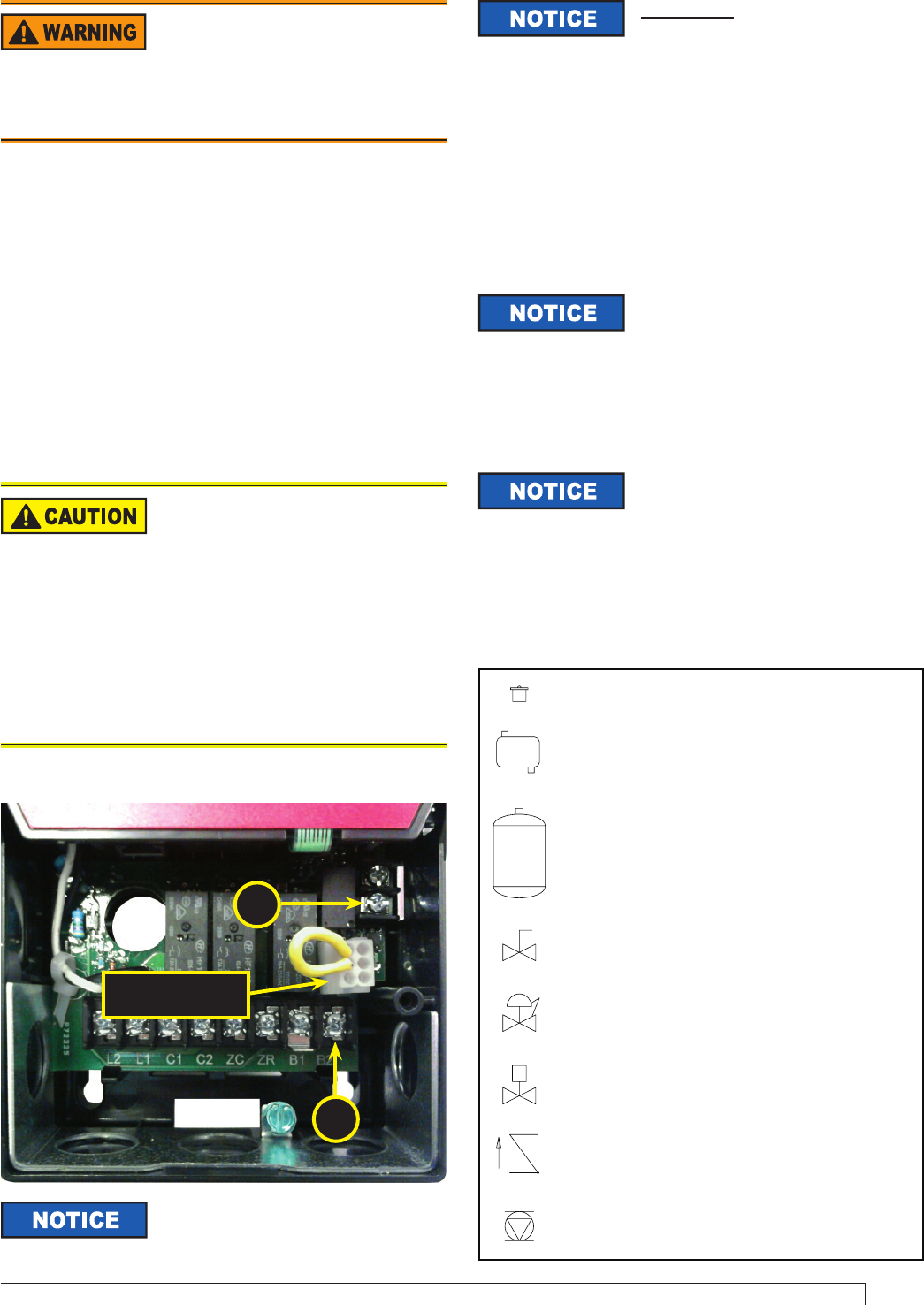
Figure 11 - TR, B2, & Vent Damper Connections
Water Flow Symbols Key (Figures 12 through 17)
Z
- Air Vent
- Air Separator
- Expansion Tank
- Isolation Valve
- Pressure Regulator
- Zone Valve
- Check Valve
- Circulator
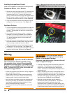
Some Thermostats Are
Polarity Sensitive
Reversed polarity could cause erratic cycling of the
boiler control.
Connect the red thermostat wire (from the RH or R
terminal of the thermostat) to the T
R
terminal on the
control.
Connect the white thermostat wire (from the W
terminal of the thermostat) to the TW terminal on the
control.
y
y
7600B only: TERMINALS TR (Z or
hot) and B2 (TV or ground) offer a
24-volt supply for operating other 24 VAC equipment on
the boiler. IMPORTANT: TO PREVENT DAMAGE TO
THE CONTROL, DO NOT OVERLOAD THE
TRANSFORMER. The AquaSmart is equipped with a
30VA transformer. Make sure that the total load,
including the burner circuit and TR & B2 connections do
not exceed 30VA.
See Figure 11.
How to calculate VA - Add all AMP ratings of 24VAC
components in this circuit and multiply sum by 24 volts.
(Example: .4 + .4 + .2 + .2 = 1.2A x 24V = 28.8 VA)
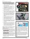
When powering multiple circulators
from the C1 and C2 terminals, take
extra care not to exceed the output’s reading. If the sum
of the full load amps of all the circulators exceeds the
output’s rating, use the C1 and C2 terminals to power the
coil of a multiple-pole contactor; the contacts of which can
be wired to switch L1 to each circulator.
Observe proper polarity when wiring
L1 and L2. If polarity is reversed, a
call for heat on the ZR input may not be recognized.
TR
B2
To wire a vent damper to the 7600B,
fi rst remove jumper plug from 6-
position receptacle and then connect 6-pin connector of
the vent damper to the receptacle. See Figure 11. Once
the 7600B is operated with a vent damper, it will not
function without one (even if the jumper plug is replaced).
6-Position Vent
Damper Receptacle