30 Instruction 3015-4275
ADM800 - Overview
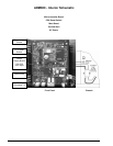
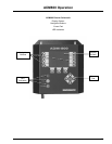
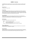
The ADM800 displays comprehensive information about the AGM300 network status and enables complete
programming control of all system operations. The prominent features of the display module are discussed
below.
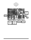
Display Screen
The display screen is a back-lit LCD.
Control Keys
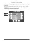
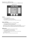
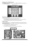
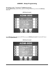
The 4 keys on each side of the display window are used to navigate between screen displays. A graphic box
that is open to the edge of the window indicates that the adjacent control key is active. The 3 keys along the
bottom of the window are also used to navigate between screens. A text block directly above the key indicates
that the key is active. An active key can be used to navigate to another screen. A graphic box, that is not open
to the edge, displays information only and the adjacent control key is inactive.
Cursor Key-Pad
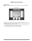
The cursor key-pad is used to move about screens, enter setup information and choose between setup
parameters. When entering information the LEFT/RIGHT keys move the cursor across an entry field, while the
UP/DOWN keys scroll data entry options. The ENTER key is used to accept data entries.
LED Indicators
The three LED indicators provide an overview of network status.
GREEN Glows when the system is operational.
RED Glows when the ADM800 detects a leak, spill, or evacuate alarm
condition anywhere on the network.
YELLOW Glows when the ADM800 detects a system fault anywhere on the network.
Internal Audible Alarm
An internal audible alarm is provided that can be programmed to sound when there is an occurrence of the
selected condition (refer to
Audible Alarm on Page 35).
External Alarms
Additionally, 2 SPDT alarm contacts are provided for the connection of external alarm devices. These alarms
are useful for alerting the user to global conditions anywhere on the network. Each relay can be programmed to
respond to alarm, fault, or monitor ON conditions (refer to
Setting Relay Parameters on Page 36).


