


PAGE 28 OPTIONAL EQUIPMENT (CONTINUED)
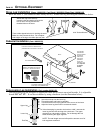
Thermostat
(Part # 99300650)
! Do not connect 120 VAC to the gas control valve or wiring of this unit.
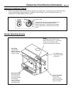
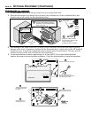
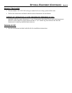
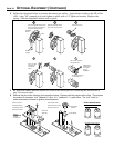
1 Route the thermostat wire through the rear panel (run it through one of the ventilation holes) and
attach to the on/off switch (see the illustration below).
Remove the green
jumper wire.
Back of
on/off
switch
Attach the quick connects
from the wire to the two posts
on the on/off switch
(orientation does not matter).
c
d
Back of on/off
switch
Open the
access door.
a
Route the wire under the burner pan
forward, underneath this clip (this
prevents it from touching the bottom
of the burner pan.
b
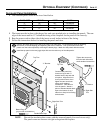
2 Pull through all the slack on the wire (you may wish to wrap the wire in electrical tape to prevent
damage to the wire). Determine a location for the thermostat that is within range of the 50' length of
thermostat wire. It should be centralized in the room and away from the heater. The wire may be
routed externally on the wall or behind the wall (preferred).
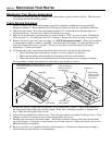
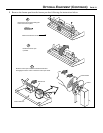
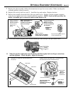
3 Cut the thermostat wire so there is approximately 6" of slack (NOTE: Do not splice thermostat wires
togetherÐthis leads to too much electrical resistance). Follow the directions below to install the thermostat.
50 60 70 80 90
50 60 70 80 90
Robertshaw
Run the thermostat wires
through the wall (cut off excess
wire, leaving 6Ó of slack).
Pull the cover off the thermostat
Expose 1/2Ó of wire and
attach to these two posts.
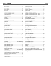
Standard
Screwdriver
Attach the thermostat to
the wall through these
two holes.
a
b
c
d
Re-attach the cover
removed in step ÒaÓ.
e