


INSERT INSTALLATION (CONT.) - For qualified installers only! PAGE 11
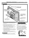
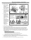
Insert Placement
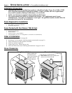
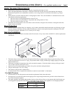
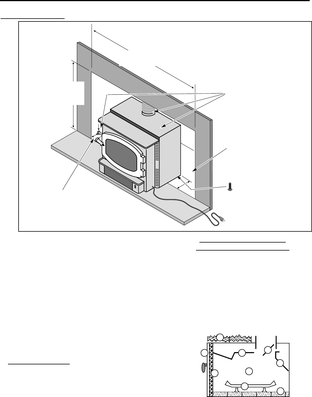
The Insert Must be
Placed 13" into the
Fireplace.
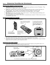
Run the power cord to
either side of the insert
along the facing.
The insert must be in place with
the gas line and vent attached
prior to installing the panels.
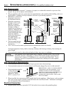
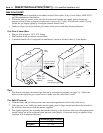
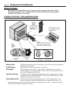
Min. 29-3/4" WIde (includes 6" for gas
line installation)
Min. 22-1/8" Tall
(includes 2" for
vent installation)
See the section "Gas Line
Installation" for details on the
location of the gas inlet.
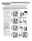
Use the leveling bolts for
fireplaces with recessed
floors (included with the
stove).
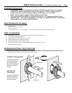
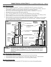
¥ Insert must be placed so no combustibles are within, or
can swing within 36" of the front of the heater (e.g.
drapes, doors)
¥ The insert may be placed inside a masonry fireplace or
listed zero-clearance (metal) fireplace
¥ The insert must be installed in a level, undamaged
fireplace (damage must be repaired prior to
installation). Use the included leveling bolts to level
the insert in fireplaces with recessed floors.
¥ The insert must maintain 10" clearance to sidewalls
(measure from the upper top)
¥ Non-combustible facing (e.g. brick, tile) must extend 8"
minimum from the side and 8" to the top of the insert
(measure from the upper top)
¥ Combustible mantles must be a minimum 17-1/2"
above the top of the insert (measure from the upper top)
Floor Protection
¥ The heater must be installed on a non-combustible
hearth and may not extend over combustible flooring
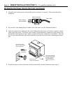
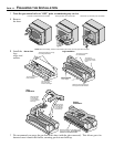
Zero-Clearance (Metal)
Fireplace Requirements:
¥ The damper ("A") and grate (with logset)
("B") must be removed (see the illustration
below)
¥ The smoke shelf ("C"), internal baffles
("D"), screen ("E"), masonry lining or
refractory ("G" & "I"), and metal or glass
doors ("F") may be removed (if applicable)
¥ The insulation ("H"), and any structured
rigid frame members (metal sides, floor,
door frame, face of the fireplace, etc.) may
not be removed or altered.
C
B
F
I
D
E
A
G
H