


9
1. Seal any unused opening in the common venting system.
2. Visually inspect the venting system for proper size and horizontal
pitch and determine there is no blockage or restriction, leakage,
corrosion or other unsafe condition.
3. Isolate the space containing the appliance(s) remaining
connected to the common venting system as much as possible
by closing all openings (windows, doors, etc.) connected to
other spaces in the building. Turn on any exhaust fans to their
maximum setting and close fireplace dampers. Note: DO NOT
operate summer exhaust fan.
4. Test fire the appliance(s) being inspected, making sure to follow
the manufacturers lighting and operating instructions.
Appliance(s) operating controls should be adjusted to provide
continuous service.
5. Check vent pressure of appliance 24 inches (61.0 cm) above
boiler vent collar. Vent pressure should be maintained between
-0.02" W. C. and -0.04" W.C. to assure proper operation. For
appliances with a draft hood, check for spillage with mirror,
smoke or other device five minutes after placing appliance in
operation.
6. After it has been determined that each appliance remaining
connected to the common venting system properly vents when
tested as outlined above, return doors, windows, exhaust fans,
fireplace dampers and other gas burning appliances to their
previous conditions of use.
All boiler venting systems shall be installed in accordance with the
National Fuel Gas Code, ANSI Z223.1 or CAN/CSA-B149.1 and .2
(and latest addendums), or applicable provisions of the local
building codes.
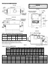
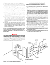
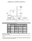
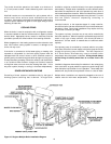
LOCATION REQUIREMENTS (INTAKE/EXHAUST)
Intake/Exhaust Installation Requirements (See figure 4):
1. The termination must be 12 inches (30.5 cm) above snow or
grade level whichever is higher.
2. Due to normal formation of water vapor in the combustion
process, horizontal terminations must not be located over areas
of pedestrian or vehicular traffic, i.e. public walkways or over
areas where condensate could create a nuisance or hazard.
This is especially true in colder climates where ice buildup is
likely to occur. A.O. Smith Corporation will not be held liable for
any personal injury or property damage due to any dislodging
of ice.
3. The minimum distance for any window, gravity air inlet to a
building, or from gas or electric meter(s) is 6 feet (1.8 m)
horizontally, 4 feet (1.2 m) below and 24 inches (61.0 cm) above.
4. The minimum distance from inside corner formed by two
exterior walls is 6 feet (1.8 m) but 10 feet (3.1 m) is
recommended where possible.
5. Maintain a minimum distance of 4 feet (1.2 m) from any soffit or eve
vent to the exhaust terminal.
6. Maintain a minimum distance of 10 feet (3.1 m) from any forced
air inlet to a building. Any fresh air or make up air inlet such as
a dryer or furnace area is considered to be a forced air inlet.
7. Avoid areas where condensate drainage may cause problems
such as above planters, patios, or adjacent to windows where
the steam from the flue gases may cause fogging.
8. Select the point of wall penetration where the minimum 1/4" per
foot (2 cm/m) of slope up can be maintained.
9. The through the wall termination kit is suitable for zero clearance
to combustible materials.
10.The mid point of the termination elbow must be a minimum of
12 inches (30.5 cm) from the exterior wall.
CAUTION
Direct venting into dead air spaces such as alleys, atriums and
inside corners can cause recirculation of flue gases.
Recirculation of flue gases will cause sooting, premature failure
of the heat exchanger and icing of the combustion air intake
during severe cold weather. To prevent the recirculation of flue
gases, maintain as much distance as possible between the
combustion air intake and the exhaust vent terminal.
Figure 4. Vent Termination Installation Clearances