


28
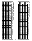
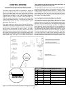
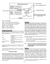
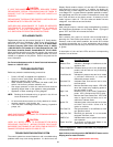
Figure 16. Display Board
High Gas Fail: Gas Pressure at Manifold too High
LWCO: Low water Cutoff activated. Not enough water.
Power Vent Fail: Not Enough Air to Close Switch
Stage One: Failure on Stage One
Stage Two: Failure on Stage Two
Stage Three: Failure on Stage Three
Stage Four: Failure on Stage Four
Yellow Parameter Set Lights
The five yellow parameter set lights allow the user to view system
set points and options. In conjunction with the four green stage
LEDs, the user can monitor and change settings on the various
stages. (See Figure 16.)
Inlet*: Temperature shown is Inlet Water
Temperature.
Outlet: Temperature shown is Outlet Water
Temperature.
Set-Point**: Indicated probe set-point is being
displayed.
Set-Point Differential: Shows differentials of each stage.
Standby: Indicates Set-Point is Satisfied. Boiler
in Idle State.
*Defaults to tank probe temperature when Dip Switch "D" on
Central Control Board is Switched to the "ON" position.
(See Figure 14.)
**Shows set-point temperatures for Inlet/Tank or Outlet in
conjunction with yellow parameter lights. See temperature
probe section below.
TEMPERATURE PROBES
All units come with two temperature probes connected to the Inlet/
Outlet header. Additionally, an optional tank probe (thermistor type)
or 24V thermostat/aquastat can be connected to the unit. The probes
can be categorized as two types: controlling probes and safety
limit probes. Controlling probes can control the staging of the
boiler. Safety limit probes are used as resettable high limit switches.
The two controlling probes are the inlet probe and the tank probe.
The function and setting of the probes is further described in the
following sections.
Outlet Probe
The Outlet Temperature/ECO probe is located on the left side of the
header and has two sets of wires embedded in it. The black wires
sense the temperature at the probe. Their output is shown on the
display screen when the "OUTLET" LED is illuminated. The red
wires control the ECO (Emergency Cutoff) which shuts down the
unit if the water temperature exceeds 250°F (121°C) and requires
a manual reset of the boiler. The outlet probe functions as a
automatically resettable high limit and is not considered a controlling
probe on the boiler, which means it cannot be set to control the
staging of the unit. Depending on the application of the boiler, the
probe is set to one of two settings. In GW applications, the maximum
Outlet Set Point is 210°F (99°C) and in GB applications it is 240°F
(115°C). The Outlet probe Set Point can be adjusted between
these two values using Dip Switch "F" on the Central Control Board
inside the control box. (See Figure 14.)
To view the current programmed temperature set-point for the Out-
let Temperature probe:
1. Press the SELECT push-button on the display board until both
the Set-Pt LED and Outlet Water Temperature LED (see
Figure 16) are illuminated.
2. The LED display will show the current set-point temperature.
Note: Under no circumstances should the Outlet/ECO be set
to exceed 210°F (99°C) in applications where the boiler
is heating potable water. Failure to observe this will
void the warranty.
Inlet Probe
The Inlet probe is located on the right side of the Inlet/Outlet header.
It has one set of blue wires embedded in it which senses the
temperature at the probe. The Inlet Probe is considered a controlling
probe and can be used to control the staging of the unit. The inlet
probe set-point is fully adjustable between the factory set minimum
value of 80°F (25°C) and a user controlled maximum value which
will depend on unit's application. In GW applications, the maximum
Inlet Set-Point is 190°F (88°C) and in GB application it is 220°F
(104°C). The Inlet probe Set-Point can be adjusted between these
two maximum values using Dip Switch "G" on the Central Control
Board which is located inside the control box. (See Figure 14.)
To change or view the current programmed temperature set-point
for the Inlet Temperature probe value: