


33
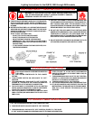
CAUTION
IF HEAT EXCHANGER MAINTENANCE REQUIRES TUBING
REPLACEMENT, SPECIAL PROVISIONS SHALL BE TAKEN TO
ENSURE THAT THE DAMAGED TUBES ARE CAREFULLY
REMOVED.
REPLACEMENT TUBES MUST BE PROPERLY INSTALLED AND
EXPANDED INTO THE ROLLED TUBE TUB.
OVER-ROLLING, MISALIGNMENT OF TUBES OR IMPROPER
TIGHTENING OF THE ASSEMBLY MAY RESULT IN LEAKS OR
DAMAGE TO THE HEAT EXCHANGER. CONTACT YOUR
A. O. SMITH DEALER FOR DETAILED INSTRUCTIONS.
REPLACEMENT PARTS
Replacement parts may be ordered through A. O. Smith dealers,
authorized servicers or distributors. Refer to the Yellow Pages for
where to call or contact (in United States) the A. O. Smith Water
Products Company, 5621 West 115th Street, Alsip, IL 60803,
1-800-433-2545 or (in Canada) A. O. Smith Enterprises Ltd., 768
Erie Street, Stratford, Ontario, Canada N5A 6T3, 519-271-5800.
When ordering parts be sure to state the quantity, part number and
description of the item including the complete model and serial
number as it appears on the product. Refer to the parts lists for
more information.
For Technical Assistance call A. O. Smith Technical Information
Center at 1-800-527-1953.
TROUBLESHOOTING
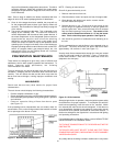
Before any extensive troubleshooting, ensure that:
• Power (120 VAC) is supplied to the appliance.
• System control (tank probe, thermostat, etc.) is calling for
appliance operation (call for heat).
• Other contacts (switches) are closed (low water cutoff, flow
switch, limit controls, pressure switches, etc.)
• Gas supply pressure is within the maximum and minimum
operating ranges listed on the appliance rating plate/label.
• Appliance is wired according to wiring diagram.
NOTE: Shorting the thermostat wiring to ground in the 24 volt
circuit will blow the 3 amp fuse.
• All wire terminals/connectors are firmly attached to valves,
modules, switches, limit controls, etc.
• There has been no damage caused by freezing, inoperative
pumps, etc.
CAUTION
MAKE SURE POWER IS DISCONNECTED FROM MAIN BREAKER
BEFORE SERVICING.
CAUTION
LABEL ALL WIRES PRIOR TO DISCONNECTION WHEN
SERVICING CONTROLS. WIRING ERRORS CAN CAUSE
IMPROPER FUNCTIONING OF UNIT RESULTING IN PROPERTY
DAMAGE, PERSONAL INJURY OR LOSS OF LIFE.
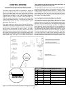
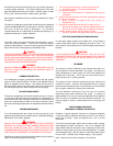
TROUBLESHOOTING IGNITION SYSTEM
The control system has several features to aid in troubleshooting
problems which may occur during operation. If a fault occurs, the
Display Board contains sixteen (16) red fault LED indicators to
help pinpoint the source of failures. In addition, the display will
inform the user on which stage the failure occurred by illuminating
a red Stage LED. In cases where the problem persists to lockout,
the appropriate red LEDs will remain illuminated and a three digit
error code will flash on the display screen. A summary of error
codes is given in table 19. The error codes are broken into two
categories: hard lockouts and soft lockout.
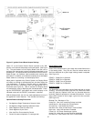
Hard Lockouts:
Hard lockouts require a manual reset accomplished by pressing
the Enter/Reset push-button on the Display Board. Cycling the
power "OFF" and "ON" will not reset the control.
Soft Lockouts:
Soft Lockouts also require a manual reset accomplished by
pressing the Enter/Reset push-button on the display board.
However, under a soft lockout condition, the control will re-initiate
an ignition process after one (1) hour provided the call-for-heat is
still present and will continue every hour until the unit is either reset
or ignites.
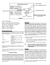
A description of the red fault LEDs and their corresponding
functions are as follows.
LED Controller Function
Blocked Flue Indicates a blockage or interference at the
appliance flue.
Temp. Probe Fail Indicates failure at one of the temperature
probes. Unit will "lock-out" only if controlling
probe fails.
Insufficient Air Indicates air pressure was too low to create
a sufficient differential to close the
differential pressure switch.
Circulate Fail Indicates water flow was too low to close
the flow switch.
Gas Valve Fail Monitors Gas Valve relay output. LED is ON
when the output relay supplying power to
the gas valve(s) is open.
High Limit Monitors ECO in the Outlet Temperature
probe. LED is ON when the ECO is open.
Flame Fail Monitors the Flame Sense Rod. LED is ON
when a signal from the flame rod is not
sufficient to indicate flame.
Igniter Fail Indicates igniter current was too low to meet
minimum value which allows trial for
ignition to continue.
Low Gas Fail Inlet gas pressure is not sufficient to close
gas pressure switch.
High Gas Fail* Manifold gas pressure is has exceeded
designed maximum value.
LWCO Fail* Indicates water level in system is too low for
safe operation.
Power Vent Fail* Air pressure at Power Vent Switch is not
sufficient for safe operation.
*Optional Equipment - LEDs will illuminate only if equipment is
connected to boiler.
Upon lockout, manually push the ENTER/RESET button on the
display panel to restart the boiler.
Verify proper operation after servicing.