


7
• THE BOILER MUST NOT BE INSTALLED ON CARPETING.
• THE BOILER SHOULD NOT BE LOCATED IN AN AREA WHERE
IT WILL BE SUBJECT TO FREEZING.
• THE BOILER SHOULD BE LOCATED NEAR A FLOOR DRAIN.
• THE BOILER SHOULD BE LOCATED IN AN AREA WHERE
LEAKAGE FROM THE BOILER OR CONNECTIONS WILL NOT
RESULT IN DAMAGE TO THE ADJACENT AREA OR TO LOWER
FLOORS OF THE STRUCTURE.
WHEN SUCH LOCATIONS CANNOT BE AVOIDED, A SUITABLE
DRAIN PAN SHOULD BE INSTALLED UNDER THE BOILER. Such
pans should be fabricated with sides at least 2-1/2" (6.5 cm) deep,
with length and width at least 2" (5.1 cm) greater than the dimensions
of the boiler and must be piped to an adequate drain. The pan
must not restrict combustion air flow.
WARNING
THERE IS A RISK IN USING FUEL BURNING APPLIANCES IN
ROOMS OR AREAS WHERE GASOLINE, OTHER FLAMMABLE
LIQUIDS OR ENGINE DRIVEN EQUIPMENT OR VEHICLES ARE
STORED, OPERATED OR REPAIRED. FLAMMABLE VAPORS ARE
HEAVY AND TRAVEL ALONG THE FLOOR AND MAY BE IGNITED
BY THE IGNITER OR MAIN BURNER FLAMES CAUSING FIRE OR
EXPLOSION. SOME LOCAL CODES PERMIT OPERATION OF GAS
APPLIANCES IF INSTALLED 18 INCHES (46.0 CM) OR MORE
ABOVE THE FLOOR. THIS MAY REDUCE THE RISK IF LOCATION
IN SUCH AN AREA CANNOT BE AVOIDED.
FLAMMABLE ITEMS, PRESSURIZED CONTAINERS OR ANY
OTHER POTENTIAL FIRE HAZARDOUS ARTICLES MUST NEVER
BE PLACED ON OR ADJACENT TO THE BOILER.
OPEN CONTAINERS OF FLAMMABLE MATERIAL SHOULD NOT
BE STORED OR USED IN THE SAME ROOM WITH THE BOILER.
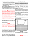
If the boiler is installed above the level of heating system terminal
units, a low water cutoff device must be installed in the boiler outlet
at the time of installation.
For installation locations with elevations above 4,500 feet
(1350 m), consult the factory.
WARNING
UNDER NO CIRCUMSTANCES SHOULD THE EQUIPMENT ROOM
WHERE THE BOILER IS INSTALLED EVER BE UNDER NEGATIVE
PRESSURE. PARTICULAR CARE MUST BE TAKEN WHEN
EXHAUST FANS, COMPRESSORS, AIR HANDLING EQUIPMENT,
ETC., MAY INTERFERE WITH THE COMBUSTION AND
VENTILATION AIR SUPPLIES OF THIS BOILER.
CHEMICAL VAPOR CORROSION
Heat exchanger corrosion and component failure can be caused
by the heating and breakdown of airborne chemical vapors. Spray
can propellants, cleaning solvents, refrigerator and air conditioning
refrigerants, swimming pool chemicals, calcium and sodium
chloride, waxes, and process chemicals are typical compounds
which are corrosive. These materials are corrosive at very low
concentration levels with little or no odor to reveal their presence.
Products of this sort should not be stored near the boiler. Also, air
which is brought in contact with the boiler should not contain any of
these chemicals. If necessary, uncontaminated air should be
obtained from remote or outside sources. Failure to observe this
requirement will void the warranty.
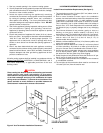
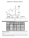
INSTALLATION CLEARANCES
Sufficient area should be provided at the front and sides of the
unit for proper servicing. For ease of service, minimum
clearances of 24" (61.0 cm) in the front and 18" (46.0 cm) on
the sides are recommended. It is important that the minimum
clearances be observed to allow service to the control box and
other controls. Observing proper clearances will allow service
to be performed without movement or removal of the boiler from
its installed location. Failure to observe minimum clearances
may require removal of the boiler in order to service such items as
the heat exchanger and burners. In a utility room installation, the
door shall be wide enough to allow the boiler to enter or to permit
the replacement of another appliance.
Two inch (5.1 cm) clearance is allowable from combustible
construction to hot water pipes. Sufficient clearance should be
provided at one end of the boiler to permit access to heat exchanger
tubes for cleaning.
Access to control box items such as the Central Control Board,
Ignition Control Boards and wiring harnesses is provided through
a panel on the left side of the unit. An 18" (46.0 cm) minimum
clearance is recommended.
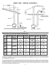
These boilers are approved for installation on noncombustible
flooring in an alcove with minimum clearance to combustibles of:
3 inches (7.6 cm) Right Side, and Back; 6 inches (15.2 cm) Top,
Front Alcove, 12 inches (30.5 cm) Left Side and 6 inches (15.2 cm)
Vent.
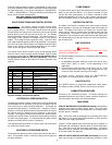
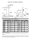
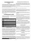
For installation on combustible flooring use the Combustible Floor
Kit. The combustible floor kit base adds 4" (10.1 cm) to the overall
height of the boiler. See figure 3.
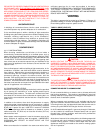
MODEL COMBUSTIBLE FLOOR KIT NO.
(GB/GW)-1000 211093
(GB/GW)-1300 211093-1
(GB/GW)-1500 211093-2
(GB/GW)-1850 211093-3
(GB/GW)-2100 211093-4
(GB/GW)-2500 211093-5
Figure 3: Boiler on Combustible Floor Base and Kit Numbers
LEVELLING
Each unit must be checked after installation to be certain that it is
level.
AIR REQUIREMENTS
WARNING
FOR SAFE OPERATION, AN AMPLE SUPPLY OF AIR MUST BE