


22
WIRING CONNECTIONS
ALL ELECTRICAL WORK MUST BE INSTALLED IN ACCORDANCE
WITH THE MOST RECENT VERSION OF THE NATIONAL
ELECTRICAL CODE/CANADIAN ELECTRICAL CODE AND MUST
CONFORM TO LOCAL REGULATIONS.
AN ELECTRICAL GROUND IS REQUIRED TO REDUCE RISK OF
ELECTRIC SHOCK OR POSSIBLE ELECTROCUTION.
Make the
ground connection to the wire provided in the electrical supply
junction box on the boiler.
Grounding and all wiring connected to this boiler must conform to
the local code authority having jurisdiction or, in the absence of
such requirements, with the
National Electrical Code, ANSI/NFPA
70 or CSA-C22.2 most recent edition.
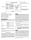
The Central Control Board and Ignition Control Boards that make
up the control system are micro-processor based which make
them vulnerable to voltage and amperage fluctuations in the power
supply. It is imperative that they be protected by a suitable
commercial-grade surge protection device.
IF ANY OF THE ORIGINAL WIRE, AS SUPPLIED WITH THE
APPLIANCE, MUST BE REPLACED, IT MUST BE REPLACED WITH
TYPE 105°C WIRE OR ITS EQUIVALENT.
The Genesis Hot Water Supply Boiler must be connected to a single
phase line source that is:
120 volts, 60 Hertz, and 30 Amps.
The system controller, other than the factory-supplied tank probe
(e. g. Honeywell Aquastat) must be wired on the low voltage side of
the 24VAC rear junction box.
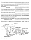
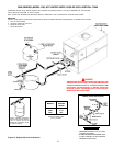
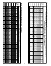
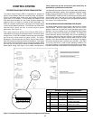
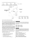
Refer to the Schematic Diagram (Figure 19) and the Connection
Diagram (Figure 20) for wire connections.
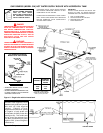
Fuse Protection
The 24 VAC circuitry is protected with a 3 amp auto fuse on the
ignition control boards and a 5 amp fuse on the Central Control
Board. If the fuse opens, a red LED located near the fuse will light
(see figures 14 and 15). If the red LED is illuminated, replace the
fuse. Repeated failure of the fuse is an indication of possible
damage to the ignition control. The 120V circuits of each ignition
control module is protected with a 10 amp fuse located inside the
control box.
Note: Four extra 3 amp fuses and one 5 amp fuse are supplied
with the boiler.
Recommended Replacement fuses:
3 Amp: Littlefuse automotive fuse PN 257003
5 Amp: Bussman Automotive fuse PN ATC5
OPERATION
IMPORTANT
Only qualified personnel shall perform the initial firing of the heater.
At this time the user should not hesitate to ask the start-up
technician any questions regarding the operation and maintenance
of the unit. If you still have questions, please contact the factory or
your local A.O. Smith representative.
Lighting and Operating instructions are included with this manual.
By using these instructions, the user may be able to make minor
operational adjustments and save unnecessary service calls.
However the user should not attempt repairs, but should contact a
service technician or gas supplier.
GENERAL
Never operate the boiler without first making sure the boiler and
system are filled with water, in addition:
For hot water supply installations:
• Make sure a temperature and pressure relief valve is installed at
the boiler and, if used, the storage tank. Also check for leaks.
For heating boiler installations:
• Make sure that the boiler and system have been purged of air
and checked for leaks.
Also be sure to check the gas piping for leaks before beginning the
initial firing of the boiler.
FILLING AND PURGING FOR HEATING
BOILER INSTALLATION
1. Fast fill system through bypass until pressure approaches
desired system pressure. Close bypass valve and permit
pressure to be established by the pressure reducing valve.
2. Vent all high points in system to purge system of air.
Provisions should be made to permit manual venting of radiators
or convectors.
FILLING FOR HOT WATER SUPPLY BOILER INSTALLATION
1. Close the systems drain valve by turning handle clockwise.
2. Open a nearby hot water faucet to permit the air in the system to
escape.
3. Fully open the cold water inlet pipe valve allowing the heater
and piping to be filled.
4. Close the hot water faucet as water starts to flow.
5. The heater is ready to be operated.