


30
Procedure for Setting Pump Delay
The Controller is factory set with a 45 second post circulate function.
With the Display Board, the user has the capability to choose
between a 45, 90, or 180 second post circulate time period, or turn
the pump on continuously. This provides flexibility in selecting the
post circulate time to meet specific installation requirements, and
improves the efficiency of the circulating pump operation.
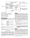
To change or view the current programmed post-circulating time:
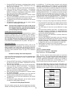
1. Press the SELECT push-button on the display board until the
LED display reads "OP" (Options). See Figure 16.
2. To enter into the options mode, press the ENTER/RESET
push-button.
3. The display will illustrate "Crcu". Enter this mode by
pressing the ENTER/RESET push-button.
4. The display will now illustrate the current post circulate time.
Press the ADJUST push-button to select the desired post
circulate time (45, 90, 180, "con").
5. When you have selected the desired post circulate time mode,
press the ENTER/RESET push-button once, this enters the
selected post circulate time into controller memory.
6. The display will automatically return to illustrating the
controlling probe temperature after five (5) seconds.
Last Error Mode
In this mode, the Display Board will illustrate the last error which
caused the unit to "lock-out". When this mode is entered the three
digit failure code that was in memory last will be displayed.
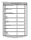
(See table 19 for error codes.) For example, if the appliance
"locked-out" due to insufficient air on stage one, the display will
show 041. To enter into this mode, perform the following steps:
1. Press the SELECT push-button on the display board until the
LED display reads "OP" (Options). See Figure 16.
2. To enter into the options mode, press the ENTER/RESET
push-button.
3. The display will illustrate "Crcu". Press the SELECT
push-button until the display illustrates "Ler". Enter this mode
by pressing the ENTER/RESET push-button.
4. The display will illustrate the last error detected by the control.
5. The display will automatically resort to illustrating the
controlling probe temperature after five (5) seconds.
Display Stage Cycle Count
The Central Control Board counts the number of cycles each stage
of the appliance has operated by counting how many times the gas
valve(s) are energized. To check the cycle count for each stage,
perform the following procedure:
1. Press the SELECT push-button on the display board until the
LED display reads "OP" (Options). See Figure 16.
2. To enter into the options mode, press the ENTER/RESET
push-button.
3. The display will illustrate "Crcu". Press the SELECT
push-button until the display illustrates "CC". Enter this mode
by pressing the ENTER/RESET push-button.
4. The display will now illustrate the current number of cycles
stage one has fired. Notice that the green Stage One LED is
illuminated. Pressing the ENTER/RESET button again will
cause the green Stage Two LED to illuminate and the cycle
count for stage two will be displayed on the screen. Cycle
counts for the other stages can be viewed in a similar fashion.
5. To reset the cycle count to zero, press the ADJUST push-
button. Press the ENTER/RESET push-button to
successfully reset the cycle count. If the ENTER push-
button is not pressed, the reset function will not be saved and
the original cycle count will continue to increment on
each gas valve operation.
6. The display will automatically return to illustrating the
controlling probe temperature after five (5) seconds.
Appliance Operating Sequence
1. When power is applied to the control system, the Display Board
will initially run through a self-diagnostic routine, and then go
into its operating mode, displaying the temperature sensed
at the Inlet probe.
2. If the Central Control Board determines the actual water
temperature at the controlling temperature probe is below the
programmed temperature set-point minus the switching
differential, and the thermostat circuit or tank probe circuit is
closed, a call for heat is activated.
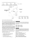
3. The control then performs selected system diagnostic checks.
This includes confirming the proper state of the ECO/High
Limit device, flow switch*, and pressure switches.
*Note: Correct water flow is vital to the operation of the boiler.
See table 4 in the Installation manual for requirements on flow,
head loss and heat exchanger pressure drop.
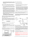
4. If all checks are successfully passed, the circulating pump
circuit is energized. Once the flow switch has closed, all
combustion blowers will energize for a 30 second pre-purge
cycle.
5. When the pre-purge cycle is complete, all blowers except stage
1 will drop out. Power is applied to the stage 1 ignitor element
for the ignitor warm-up period.
6. The control will verify ignitor current. After the verification, the
gas valve will open, allowing gas to enter the burner.
7. After an additional 1 second, the control will monitor the flame
sense probe to confirm a flame is present. If a flame is not
verified within 4 seconds, the gas valve is immediately closed.
The control will initiate an 15 second inter-purge period and
return to step 2, unless dip switch "B" is in the "ON" position,
see fig. 14, in which case it will proceed to "lock-out".
8. If a flame is confirmed, stage two will be activated. The blower
associated with stage two will start. Once the blower has
been proven, igniter two will begin its warm-up period.
(This is true on all units except the 1000 which has only one
igniter.) After the igniter current has been proven, stage two
will begin a trial for ignition.
9. Stage three will activate after flame is proven on stage two. If
applicable, the blower associated with stage three will begin.
Once the blower has been proven, a trial for ignition will begin
on stage three. If flame is not proven, there will be a 15
second interpurge on stages with an associated blower. The
boiler will then begin additional trials for ignition. On stages
without an associated blower, a five second delay will occur
before the gas valves are opened for additional trials for
ignition.
Note: Stages on which no blower or igniter is present will
bypass the blower and igniter proving periods. The gas valves will
open five seconds after a call for heat is initiated on the stage.
10. All stages will remain running until the set point for a given
stage is satisfied. If all stages are initiated, stage four will