29
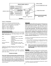
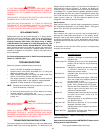
1. Press the SELECT push-button on the display board until both
the Set-Pt LED and Inlet Water Temperature LED (see
Figure 16) are illuminated.
2. The LED display will show the current set-point temperature.
3. Press and hold the ADJUST push-button. The displayed
temperature will either increase or decrease. To alternate
between increasing or decreasing the temperature, release
then press and hold the ADJUST push-button.
4. When the desired set-point temperature is reached, release
the ADJUST push-button.
5. Press the ENTER/RESET push-button once, this enters the
selected set-point temperature into controller memory.
6. The appliance will now control the temperature to the desired
set-point value.
7. For setting the stage differentials, see the section labeled
Procedure for Setting Stage Differential.
NOTE: The boiler must complete a full cycle in order for the
new setting to take effect. If the unit is turned off prior
to a complete cycle the setting will be lost and the
previous setting will remain in effect.
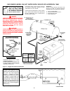
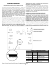
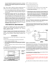
24 VAC System Controller (Optional)
A 24 VAC thermostat/aquastat can be implemented as a system
controller on Genesis units. The connection for such devices is
located in the 24 VAC junction box at the rear of the unit. A 24 VAC
thermostat/aquastat can only be used as an "On/Off" switch for the
unit. The actual controlling of the staging will be through either the
inlet or tank probe. To use a 24 VAC system controller, dip switch "E"
on the CCB must be switched to the "on" position. See Figure 14.
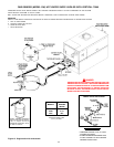
Tank Probe (Optional)
In addition to the Inlet and Outlet/ECO Probes, units can be
optionally equipped with a tank Probe. The connection for the tank
probe is located in the 24 VAC junction box at the rear of the unit.
The tank Probe can be configured to control the staging of the unit.
See Tank Probe Installation section on page 17 for additional
information.
Procedure for Setting Tank Probe Temperature
If you have a GW hot water supply boiler, and have installed the tank
probe, below are the instructions on how to adjust the water
temperature set-point.
1. Press the SELECT push-button on the display board until both
the Set-Pt LED and Inlet Water Temperature LED (see
Figure 16) are illuminated.
2. The LED display will show the current set-point temperature.
3. Press and hold the ADJUST push-button. The displayed
temperature will either increase or decrease. To alternate
between increasing or decreasing the temperature, release
then press and hold the ADJUST push-button.
4. When the desired set-point temperature is reached, release
the ADJUST push-button.
5. Press the ENTER/RESET push-button once, this enters the
selected set-point temperature into controller memory.
6. The appliance will now control the temperature to the desired
set-point value.
7. For setting the stage differentials, see the section labeled
Procedure for Setting Stage Differential.
Procedure for Setting Stage Differential
Once the system control and set-point temperature has been
entered, the switching differentials for the staging of the unit must
be established. To facilitate proper operation and maximize
appliance performance, each stage has a programmable
operating switching differential or “hysteresis” about the set point.
This means a call for heat for a particular stage will become active
when the water temperature measured at the controlling
temperature sensing probe drops to the set-point value minus the
switching differential value. It is necessary to set three set-point
differential values for three stage units and four for four stage. The
burner will remain on until the water temperature measured at
controlling probe reaches the stage set-point value. The switching
differential value is fully programmable from 0° F to 20°F (0°C to
11°C) using the push-button(s) located on the Display Board.
To change or view the current programmed switching differential:
1. Press the SELECT push-button on the display board until both
the Set-Pt Diff. and green Stage One LED (see Figure 16) are
illuminated.
2. The LED display will show the current differential for stage
one.
3. Press and hold the ADJUST push-button. The displayed value
will either increase or decrease. To alternate between
increasing or decreasing the differential, release then press
and hold the ADJUST push-button.
4. When the desired Set-Pt differential is reached, release the
ADJUST push-button.
5. Press the ENTER/RESET push-button once, this enters the
selected set-point deferential into controller memory. To view
the Set-Pt minus the Set-Pt differential, press and hold the
"ENTER" push-button. This will be the "turn-on" temperature
for Stage One and the "turn-off" temperature for Stage Two.
6. Repeat steps 2 through 5 for the rest of the stages.
7. The appliance will now control temperature utilizing the
desired differentials.
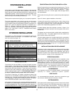
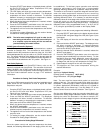
Example:
Application: Hydronic Heating
Desired System Temperature: 185°F (85°C)
Stage Differentials: 5°F (3°C) per Stage.
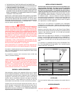
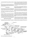
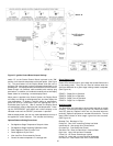
Note: The user must first choose which probe is to control the
staging of the unit. The controlling probe will be either the inlet or
tank probe. (If the tank probe is used to regulate loop temperature
in hydronic applications (GB Models), make sure it is located on
the return side of the closed loop.) Use Dip Switch "D" on the
Central Control Board to make this selection. See Figure 14.
Set the stage differentials using the procedure described in the
Procedure for Setting Stage Differential section of the document.
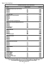
Setting the control as described in the above example (5°F
differentials for each stage) will give the following stage set-points.
Stage One
Off Temperature: 185°F (85°C)
On Temperature: 180°F (82°C)
Stage Two
Off Temperature: 180°F (82°C)
On Temperature: 175°F (79°C)
Stage Three
Off Temperature: 175°F (79°C)
On Temperature: 170°F (77°C)
Stage Four
Off Temperature: 170°F (77°C)
On Temperature: 165°F (74°C)