


27
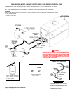
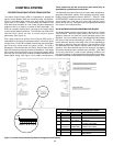
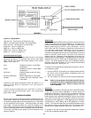
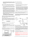
switch "D" on the Central Control Board is placed in the "ON"
position, it will show the temperature at the tank probe. (See Figure
14.) The push buttons on the Display Board allow the user to
program and view several system parameters described in the
following text. The Display Board is connected to the Central Control
Board through a 6 conductor cable assembly with modular plug
terminations. In addition, an 8 conductor modular jack on the Display
Board allows for connecting a remote display board.
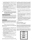
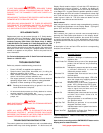
When power is applied to the Control System, the Display Board
will initially run through a self-diagnostic test, and then display the
inlet temperature. To display a specific setting or temperature,
press the SELECT push-button until the appropriate LED is
illuminated (see Figure 16). After 5 seconds, the Display Board
will automatically revert to displaying the Inlet temperature. Press-
ing the ENTER/RESET push-button will hold the display in the
indicated mode until the SELECT push-button is pressed.
With the display board, the user can make adjustments to many of
the appliance’s control features. This includes the following:
Options/Features Setting Procedures
• Set Appliance Stage Temperature Set-point Value
• Set Appliance Stage Switching Differential Value
• Select Appliance Post-Circulate Time
• Check Appliance Cycle Count
• View Last Error Encountered by Control
• Control the water temperature in a storage tank
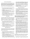
Green Status Lights
Green LEDs indicate when a given stage has sensed flame and is
in the heating state. They also are used to indicate when the
Set-Point differential for a given stage is being viewed or adjusted.
(See Figure 16.)
STAGE 1: Stage One in Operation
STAGE 2: Stage Two in Operation
STAGE 3: Stage Three in Operation
STAGE 4: Stage Four in Operation
Red Fault Lights
The Red LEDs are illuminated to show faults and help in trouble
shooting. There are three faults (High Gas Fail, LWCO and Power
Vent Fail) listed as "Optional" which are only functional when the
particular "Optional" equipment is included with the boiler. The red
stage LEDs indicate on which stage a given fault has occurred.
(See Figure 16.)
Blocked Flue: Blockage in Flue
Probe Fail: One of the controlling Probes has failed
Insufficient Air: Not enough Air to Close Switch
Circulate Fail: Flow Switch Not Closed
Gas Valve Fail: Relay for Gas Valve in Incorrect State
High Limit: High Limit has been Exceeded
Flame Fail: No Flame Sensed upon Ignition
Igniter Fail: Igniter did not reach Minimum Amperage
Low Gas Fail: Gas Pressure too low to Close Switch
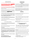
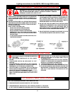
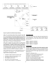
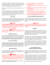
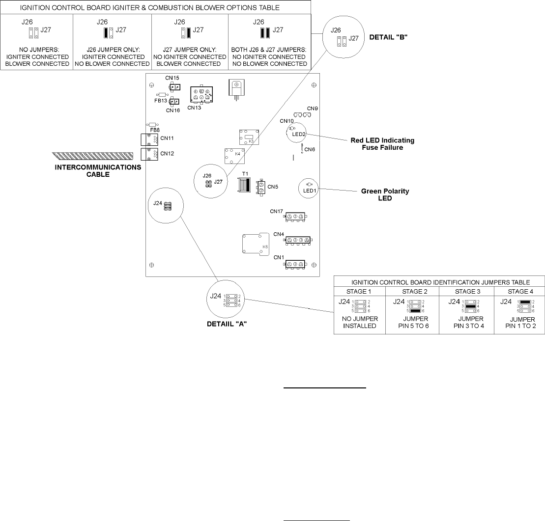
Figure 15. Ignition Control Board Jumper Settings