


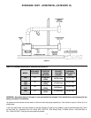
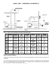

5
Example: A Genesis boiler is rated at 1,300,000 Btu/hr. input at sea
level. At an altitude of 5,000 (1500m), the prejet orifices will decrease
the input rate by 20% (= 4% x 5) to a new rating of 1,040,000 Btu/hr.
(= 80% x 1,300,000 Btu/hr.) The input reduction is achieved by the
prejet orifices through self-regulation.
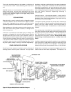
FEATURES/CONTROLS
MULTI-STAGE FIRING AND CONTROL SYSTEM
ALL MODELS - The control system consists of three basic
components: 1) Central Control Board 2) Ignition Control Board
and 3) Display Board. The Central Control Board and Ignition
Control Boards are located in the control box and can be accessed
through panels on the left side and top of the unit. The Display
Board is attached to the front jacket panel. The control system is a
multi-stage control capable of managing three or four ignition
stages. Three stage models include the 1000, 1300 and 1500.
Four stage models include the 1850, 2100 and 2500. Every system
will have one Central Control Board, one Display Board and either
three or four Ignition Control Boards depending on the model.
There will be one Ignition Control Board per stage.
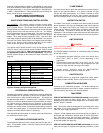
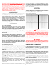
The central control board contains a strip of dip switches which
allow the user to control several system variables. Table 5 shows
a summary of these options. Make sure the dip switches are in
the appropriate position for the unit's application. Consult the
Control System section of the manual for more information, see
page 26.
Figure 2. Summary of Dip Switch Options.
DIFFERENTIAL PRESSURE SWITCH
The differential pressure switch ensures that a sufficient differential
exists between the air pressure in the pre-mix chamber and the
inlet of the burner for safe, low NOX combustion. The switch has
two pressure taps marked "+" (positive) and "-" (negative). Silicone
tubing is run from the positive pressure tap of the switch to a tap on
the control panel to measure the air pressure in the pre-mix
chamber. The negative pressure tap measures the pressure taken
at the burner's auxiliary tube. Connections can be seen by removing
the lower front jacket panel. It is important that this panel remain
sealed at all times while the boiler is operating.
This differential pressure switch is normally open and closes when
the combustion blower starts.
BLOCKED FLUE PRESSURE SWITCH
The blocked flue pressure switch ensures that the flue gas vent is
clear. This pressure switch is normally closed and only opens on
the fault conditions.
FLAME SENSOR
The flame sensor acts to prove the flame has carried over from the
ignitor to the right-most burner. If no flame is sensed, the gas
valve(s) will close automatically. If no flame is sensed on three
ignition trials the boiler will lock out. Upon lockout, manually push
the ENTER/RESET button on the display panel to restart the boiler.
WATER FLOW SWITCH
The Water Flow Switch is installed at the boiler outlet to prevent
burner operation in the event of inadequate water flow through the
boiler. The Water Flow Switch is a single pole, normally open
switch that will close its contacts when increasing water flow rate
is encountered. This switch is factory-set, but may require field
adjustment. The contacts will open when the flow rate drops below
the adjusted setting and the gas valve(s) will close turning off the
gas to the burners.
LIMIT CONTROLS
CAUTION
LIMIT CONTROLS ARE SAFETY DEVICES AND ARE NOT TO BE
USED AS A THERMOSTAT.
The GB/GW models incorporate an outlet water probe consisting
of two limit controls:
1. An adjustable automatic reset limit control, that can be set to
either 210°F (99°C) or 240°F (115°C) depending on the
application.
2. A fixed manual reset limit factory set at 250°F (121°C). If the
manual reset should open due to high temperature the gas
valves will close and the unit will go into lockout.
If lockout occurs, manually push the ENTER/RESET
push-button on the display panel to restart the boiler.
ON/OFF SWITCH
The ON/OFF switch is a single-pole, single-throw rocker switch.
The switch provides 120VAC from the line source to the boiler.
COMBUSTION AIR BLOWER
Provides air for combustion process. The blower settings are
adjustable through the use of the air shutter, however, blowers are
set at the factory and should not need adjustment.
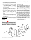
TANK PROBE
FOR HOT WATER SUPPLY SYSTEMS (GW models), A tank probe is
supplied with each hot water supply boiler. The inlet water
temperature will default to the tank temperature on the display when
the tank probe is installed.
Note: Tank Probe must be designated as controlling probe using
Dip Switch "D" on Central Control Board before it can be used for
(GW) hot water supply applications.
"Pigtails" of field-supplied wires should be spliced to "pigtails" of
tank probe and connected to terminal block in the 24 volt junction
box. See figure 12 for the tank probe installation. Follow the
instructions for the operation and temperature setting procedures
for the tank probe (see page 29).
FOR HOT WATER HEATING SYSTEMS (GB models) Due
to the
many various types of systems and operating conditions, a tank
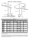
DIP SWITCH CONFIGURATION TABLE
SW1 OFF ON SELECTION:
A 3 STAGE 4 STAGE EITHER 3 OR 4 STAGE SYSTEM
B 3 TRIALS 1 TRIAL EITHER 3 OR 1
C NO IRI IRI WHETHER SYSTEM IS IRI OR
GAS VALVE GAS VALVE STANDARD
D INLET TANK INLET OR TANK AS
CONTROLLING PROBE
E NO EXTERNAL EXTERNAL WHETHER EXTERNAL
THERMOSTAT THERMOSTAT THERMOSTAT IS USED
F OUTLET 210°F OUTLET 240°F OUTLET MAXIMUM TEMPERATURE
G 190°F 220°F MAX. SET-POINT TEMPERATURE
H DEGREES °F DEGREES °C EITHER °F OR °C FOR DISPLAYED
TEMPERATURE