


7
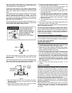
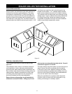
TABLE 1:
Item Component Function
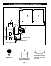
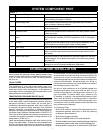
1 Solar collector Absorbs the sun’s heat energy and transfers this to the heat transfer
fl uid circulating through the collector
2 Solar storage tank Stores potable water heated by solar generated heat or installed
back-up electric resistance element
3 Heat exchanger (Not Shown) Transfers the heat from the collector loop to the potable water in the
solar storage tank
4 Expansion tank Allows for the expansion and contraction of the heat transfer fl uid as
it heat and cools.
5 Temperature and Pressure relief
valve
Required by plumbing code to automatically open and dump water if
the storage tank exceeds 150 PSI of pressure or 210° F in tempera-
ture
6 Air vent Purges air from the collector loop fl uid during the installation and is
shut off later on to prevent glycol losses in steam phase.
7 Drain valve Used to drain the heat transfer fl uid from the collector loop
8 Mixing valve Used to temper hot water from the solar storage tank with cold inlet
water to maintain appropriate temperature hot water delivered from
the system
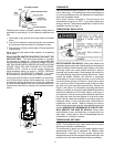
9 Solar pump station Controls the fl ow of heat transfer fl uid from the collectors to the tank/
heat exchanger. For a detailed description of the solar pump station
see page 20.
10 Temperature sensor Tank and collector sensor work together to turn the circulating
pump(s) on and off at preset temperature differentials
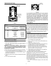
SYSTEM COMPONENT PART
STORAGE TANK INSTALLATION
Never operate the electrical heating element without being
certain the solar water heater is completely filled with water.
If any air is left in the top of the tank, the heating element
will burn out.
LOCAL CODES
The installation of this solar water heater must be in
accordance with these instructions and all applicable local
codes and electric utility requirements. In the absence of
local codes, install in accordance with the latest edition of the
National Electrical Code (NFPA-70).
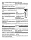
TEMPERATURE-PRESSURE RELIEF VALVE
For protection against excessive pressures and temperatures
in this water heater, install temperature-pressure protective
equipment required by local codes, but not less than a
combination temperature-pressure relief valve certified by
a nationally recognized testing laboratory that maintains
periodic inspection of production of listed equipment or
materials, as meeting the requirements for Relief Valves for
Hot Water Supply Systems, the latest edition of ANSI Z21.22.
This valve must be marked with a maximum set pressure not
to exceed the marked hydrostatic working pressure of the
water heater (150 lbs./sq. in.).
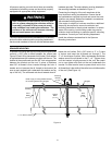
Install the temperature-pressure relief valve directly into the
fitting of the water heater. Position the valve downward and
provide a discharge pipe that must terminate a maximum
of six inches above a fl oor drain or external to the building.
In cold climates, it is recommended that the discharge pipe
be terminated at an adequate drain inside the building. Be
certain that no contact is made with any live electrical part.
The discharge opening must not be blocked or reduced in size
under any circumstances. Excessive length, over 15 feet, or
use of more than two elbows can cause restriction and reduce
the discharge capacity of the valve.
No valve or other obstruction is to be placed between the
temperature-pressure relief valve and the tank. Do not
connect tubing directly to discharge drain unless a 6” air
gap is provided. To prevent bodily injury, hazard to life
or damage to property, the temperature-pressure relief
valve must be allowed to discharge water in quantities
should circumstances demand. If the discharge pipe is not
connected to a drain or other suitable means, the water flow
may cause property damage.
The Discharge Pipe:
• Shall not be smaller in size than the outlet pipe size of the
temperature-pressure relief valve, or have any reducing
couplings or other restrictions.
• Shall not be plugged or blocked.
• Shall be of material listed for hot water distribution.
• Shall be installed so as to allow complete drainage of both the
temperature-pressure relief valve, and the discharge pipe.
• Must terminate a maximum of six inches above a floor drain