


26
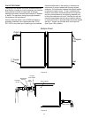
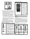
System Monitoring Display
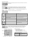
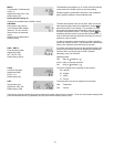
Complete monitoring display
The system monitoring display consists of 3 blocks: channel indication, the toolbar, and
system screen.
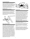
Channel indication
The channel indication consists of two lines. The upper line is an alphanumeric 16
segment indication in which the channel name or menu item is shown. The lower
7 segment indication shows the channel value and the adjustment parameters are
indicated.
Temperatures are indicated in °F / °C, Temperature differences are indicated in °F / K
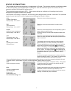
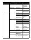
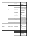
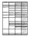
Toolbar
The symbols in the toolbar indicate the current system status
SYMBOL STANDARD FLASHING
Relay 1 active
Relay 2 active
Maximum tank limit reached / maximum tank
temperature exceeded.
Collector cooling function active
Antifreeze – function activated Collector minimum temperature reached
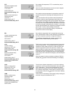
Collector security shutdown or tank security
shutdown active (max temperature reached).
Sensor error
Manual operation active
Displayed channel indication is adjustable Adjustment mode for displayed channel
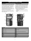
System Screen
The system screen (active system scheme) shows the scheme selected on the
controller. It consists of several component symbols, which are – depending on the
current status of the system – either fl ashing, permanently shown or hidden.
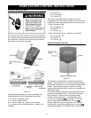
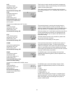
Blinking control symbols
Pump is blinking while running•
Sensors are blinking if the respective sensor •
indication channel is selected
Sensors are quickly blinking if there is a sensor error•
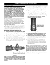
Operation control lamp indication
Constantly green: system operation normal
Red/green blinking: initialization phase, manual
operation
Red blinking: sensor error