


24
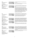
Turn on the supply water and open the fill valve (P) 14.
then leave running for 15 minutes to flush debris out
of the solar loop
After the 15 minute flush turn off the supply water 15.
at the source and allow the system to drain. When
water stops flowing out of the discharge hose close
the fill valve (P)
Close the drain valve (T) on the pump station and 16.
move this hose to the drain valve that was installed at
the lowest point of the solar loop (near the bottom of
the tank)
Open this drain valve with a flat head screw driver 17.
and open the fill valve (P) slowly to vent the system
and allow the remaining water to drain out. In order
to vent the system completely it is necessary to open
the flow restrictor (S) - turn with flat head screwdriver
until vertical.
FILLING
Close the lower loop drain valve with a flat head 18.
screw driver and move the discharge hose from the
lower valve to the drain valve (T) on the pump station
and open this valve. The other end of the discharge
hose will be placed into the glycol solution container.
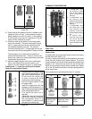
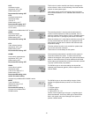
Turn the return ball valve (J) to 0° (vertical) so that 19.
flow is only allowed in the proper direction.
Connect a fill hose from the glycol container to a 1/2 20.
HP transfer pump and another hose from the transfer
pump to the fill valve (P) then open this valve.
Open the cap on the automatic air vent at the top 21.
of the collector array 3 full turns counterclockwise
to vent any air in the solar loop (do not remove cap
completely).
In order to flush as much air as possible from the 22.
system, turn on the transfer pump to fill the system
with the glycol solution and allow to circulate for
15 minutes or until no bubbles are returning to the
collector.
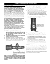
Remove the cap from the front of the airstop (I) and 23.
open the vent with a flat head screwdriver. This will
release air that has been captured by the system
during circulation. Cover small outlet port with a rag
as fluid will be ejected after the air is evacuated.
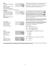
Turn the supply ball valve (Q) to 0° (vertical) so 24.
that flow is only allowed in the proper direction and
ensure that the flow restrictor (S) is completely open
(vertical)
With the transfer pump still running close the drain 25.
valve and allow to system to rise to an operating
pressure of 30 psi on the pressure gauge then close
the fill valve and turn off the pump. If the pressure
has exceeded 30 psi after the pump is off then slowly
open the drain valve and relieve pressure until the
pressure gauge reads 30 psi, then close the drain
valve.
Remove the fill and drain hoses and close the fill and 26.
drain valves (P,T) with the caps provided.
Plug in the solar pump station to a 115V outlet and 27.
turn the pump on using the manual mode (see Pump
Station Control Instruction section).
Adjust the pump speed using the pump speed 28.
selector (R) to the lowest setting possible to set the
system flow rate equal to or higher than the final
system flow rate. If the flow rate is higher than
necessary turn the flow restrictor (S) on the flowmeter
with a flat head screwdriver to reduce the flow to the
actual required:
2 panel system: 1.4 gpm
3 panel system: 2.1 gpm
Cycle the pump on and off in manual mode to check
whether the starting torque is sufficient with the pump
speed selected. If flow does not start properly a
higher speed may need to be selected and the flow
reset to the proper level with the flow restrictor (S)
Again check the installation for leaks and ensure both
ball valves are open completely.
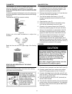
Replace the front cover (D) and re-insert the red 29.
temperature gauge (C) in the return ball valve (J) and
the blue temperature gauge (E) in the supply ball
valve (Q).
Set the controller to operate in automatic mode (see 30.
Pump Station Control Instruction section).
After the system has been running for several days 31.
the cap on the automatic air vent at the top of the
collector array should be closed by turning the cap
counterclockwise by hand until tight.
DRAINING
Open the check valves in the supply and the return 1.
ball valves (J,Q) by turning the ball valves to position
45° with an appropriate wrench
Place a temperature-resistant container under the 2.
drain valve at the lowest point of the solar thermal
installation (usually near heat exchange coil at the
bottom of the tank).
Open the drain valve at the lowest point of the solar 3.
thermal installation.
Open the automatic air vent at the top of the collector 4.
array 3 full turns counterclockwise by hand (cap
should not be completely removed). This will serve
as a vacuum break to aid in draining.
Dispose of the solar fluid observing any local code.5.