


22
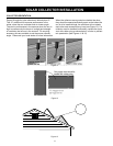
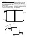
FLOW CLOSED
Figure 25
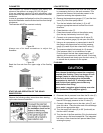
Check and set the pressure of the air bladder in the 10.
expansion tank to 25 psi. If the pressure is higher
bleed pressure out until it is correct. If the pressure
is too low add air by use of a compressor or bicycle
pump until the pressure is correct.
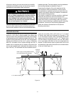
Plumb the solar pump station to the storage tank 11.
and to the collector: The tank connections should
use ¾” copper pipe and can be connected using
the threaded adaptors provided. The collector
connections should use ½” copper pipe and can be
connected with the the compression fittings provided.
The total piping run in the solar loop should not
exceed 200 equivalent feet. Failure to limit the line
length may cause poor system performance and lead
to premature pump failure.
Add the supplied copper drain valve to the lowest 12.
point in the collector loop (near the tank by the
bottom coil outlet labeled “to pump” in most cases)
Installing the ½” copper to and from the collector
using the compression fittings.
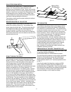
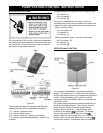
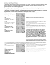
Push the union nut 1. d and the cutting
ring e onto the copper pipe c. The
pipe must protrude at least 3/8”
(3 mm) from the cutting ring
in order to ensure the force
transmission and the sealing.
Insert the support sleeve 2. f into
the copper pipe.
Insert the copper pipe with the 3.
plugged-on individual parts (d, e
and f) all the way into the housing
of the compression fitting g.
First screw the union nut 4. d
manually.
Tighten the union nut 5. d by rotating
one full turn. Hold the housing of
the compression fitting g to
avoid rotation in order to avoid
damaging the sealing ring.
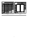
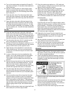
Figure 26
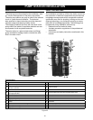
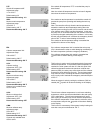
PLUMBING CONFIGURATION
1
2
K
H
3
4
V
L
½” copper tube - from 1.
the collector outlet
(top) to the collector
return compression
fitting (K)
½” copper tube – from 2.
the collector inlet
(bottom) to the collector
supply compression
fitting (L)
¾” copper tube – from 3.
the upper tank coil
inlet marked “from
collector” to the tank
supply threaded fitting
(H)
¾” copper tube – 4.
from the lower tank
coil outlet marked
“to pump” to the tank
return threaded fitting
(V)
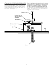
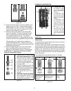
Figure 27
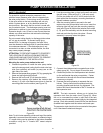
FUNCTION
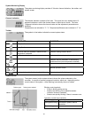
Check valves
The solar station is equipped with check valves in the supply
and the return ball valve (J, Q).
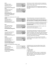
For filling, venting and flushing of the installation the check
valves must be turned to the correct position. To set the
proper position for the check valves take off the temperature
gauges (C, E), remove the top cover (D) and turn the ball
valves into the proper position using a wrench (see Figure
28). In the 45° position the balls in the ball valves push the
check valves open.
During operation the ball valves must be in 0° position.
0° 45° 90°
Check valve is
operating, flow
only in flow
direction
Check valve is not
operating, flow in
both directions.
Ball valve
closed,
no flow.
Figure 28