


25
PUMP STATION CONTROL INSTRUCTIONS
CONTROL INSTRUCTIONS
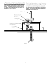
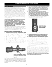
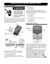
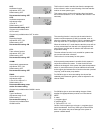
Prior to operation of the control on the solar pump station
the collector and tank temperature sensors must be prop-
erly connected. Remove the control cover and connect
the sensors to the proper terminals.
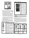
Figure 32
Figure 33
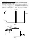
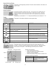
The temperature sensors should be connected to the
following terminals with no dependence on polarity:
1 / 2 = sensor 1 (collector outlet)
3 / 4 = sensor 2 (tank bottom)
5 / 6 = sensor 3 (tank top – optional, not included)
7 / 8 = sensor 4 (return flow temperature – optional, not
included)
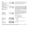
The power supply is connected to the following terminals:
19 = Neutral - N
20 = Line power - L
12 = Ground
The control is equipped with two relays, one for the
integrated pump in the solar pump station and one for use
in specialty custom applications requiring a second pump:
• Relay 1 (primary pump)
18 = Line power - R1
17 = Neutral - N
13 = Ground
• Relay 2 (secondary pump – optional, not included)
16 = Line power - R2
15 = Neutral - N
14 = Ground
OPERATION AND FUNCTION
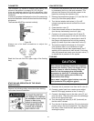
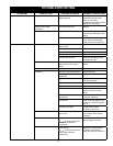
Figure 34
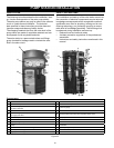
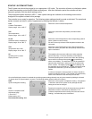
The controller is operated by 3 pushbuttons below the
display. The forward key (1) is used for scrolling forward
through the indication menu or to increase the adjustment
values. The backwards key (2) is used for scrolling
backward through the indication menu or to decrease the
adjustment values.
For system settings adjustment press the forward key to
reach the last display channel. Then hold the forward
button down for 2 seconds and the system setting
screens can then be shown. If an adjustable value
is shown on the display is indicated. To change
the set value press the Set button (3) so that
flashes. Adjust the value using button 1 or 2 until the
desired value is shown then press button 3 so that
permanently appears. The adjusted value is now saved.