


19
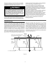
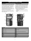
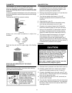
COLLECTOR PIPING DETAIL
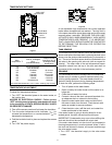
The outlets of the collector are 1” copper pipe nipples
(Figure 19). They should be piped as shown with
provisions for an automatic air vent. The air vent must be
oriented vertically as this must be the highest point in the
system in order for air to escape. This will prevent air lock
and subsequent loss of system effi ciency. Tefl on tape
or high temperature, high quality pipe sealant should be
used when making threaded connections.
The collector inlets should be piped similarly but without
the automatic air vent.
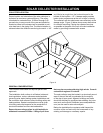
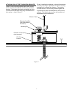
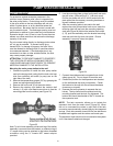
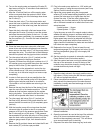
SENSOR MOUNTING AT COLLECTOR
The angled collector heat sensor is mounted to the
outlet of the collector (Figure 20). The stainless steel
screw clamp should be used. The entire sensor should
be wrapped thoroughly with the insulating stretch tape
so that the sensor is isolated from the outside air. If
possible route the sensor wire through the roof fl ashing
and connect the sensor wire to the sensor extension wire
provided with wire nuts.
Figure 20
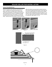
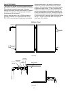
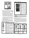
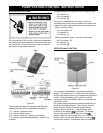
PIPING THROUGH THE ROOF
Piping through the roof should be weatherproofed as
shown in Figure 21. Three-quarter inch holes are drilled
through the roof on the same plane as the supply and
return header pipes. Do not drill the hole above the
supply header of the collector. This will prevent the
collector from draining. Placing the hole below the supply
header is acceptable, but it is more aesthetic if it is
located on the same plane. The fl ashing plate is placed
over the hole with its base cemented and nailed to the
roof and its upper edges slid under the adjoining shingle.
A hole 1/2 the diameter of the supply tube should be
cut in the top of the fl ashing gasket and the copper tube
supply and return line is then pushed up through the hole
in the fl ashing. The same procedure is then repeated for
the return line and fl ashing. The sensor wire should also
be run through the return fl ashing by piercing a small hole
in one of the corner nipples. Caution - making the hole
for the copper pipe or the sensor wire too big will prevent
a proper seal. The return and supply lines should be
supported under the roof to prevent undue stress on the
piping assemblies at the collector.
Sensor Wire
(To Collector)
Figure 21
PIPE INSULATION
The collector loop piping (exterior and interior) must be
well insulated with a high quality fl exible EPDM closed
cell insulation to minimize heat loss. The wall thickness
of the pipe insulation should not be less than ¾”. A 1” wall
thickness is required in all areas prone to annual hard
freeze conditions. When it comes to pipe insulation the
rule is simple: thicker is better. The specifi ed insulation
material is Armacell UT Solafl ex or equivalent.
To the extent possible, slide the insulation material over
the pipe without cutting or taping. All butt joints must be
sealed with high temperature contact adhesive. The use
of rigid polyethylene pipe insulation is prohibited. All
outdoor insulation should be protected from moisture
and Ultraviolet deterioration by either paint or foil
tape. Insulation to complete the outdoor portion of the
installation has been provided.
PREPARATION OF THE HEAT TRANSFER FLUID
Pour 100% Propylene Glycol into a large clean bucket. Add
an equivalent amount of distilled or
de-mineralized water for a 50/50 solution by volume.
The use of regular tap water as a mixing agent is prohibited.
Distilled or de-mineralized water is often available from
grocery stores and drugstores. This solution provides
freeze protection down to -30° F and burst protection down
to -60° F.
Use of heat-transfer fl uid other than a maximum 50/50
mix by volume of Propylene Glycol and distilled or de-
mineralized water is not permitted. Use of any heat-transfer
fl uid other than that specifi ed by the appliance manufacturer
will void warranty, and may result in poor performance,
equipment damage, or risk to health and safety.