


21
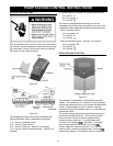
SAFETY EQUIPMENT
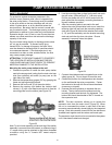
For protection against excessive pressures in the
collector loop a pressure relief valve is integrated into
the solar pump station. Drain tubing must be installed
in the valve outlet so that any discharge will exit only
within 6 inches above, or at any distance below the
structural fl oor. Be certain that no contact is made with
any live electrical part. The discharge opening must not
be blocked or reduced in size under any circumstances.
Excessive length, over 15 feet, or use of more than two
elbows can cause restriction and reduce the discharge
capacity of the valve.
Do not connect tubing directly to discharge drain unless
a 6” air gap is provided. To prevent bodily injury,
hazard to life, or damage to property, the relief valve
must be allowed to discharge fl uid in quantities should
circumstances demand. If the discharge pipe is not
connected to a drain or other suitable means, the fl uid
may cause property damage.
ATTENTION: TO PREVENT DAMAGE TO PROPERTY,
THE LOCATION OF INSTALLATION MUST BE DRY,
LOAD-CARRYING AND FROST-PROOF TO PREVENT
MATERIAL DAMAGE TO THE INSTALLATION.
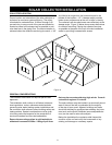
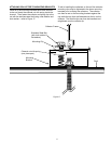
Mounting the solar pump station to the wall
Choose the position to install the solar pump station 1.
next to the storage tank (noting that the tank solar loop
inlet (from collector) and outlet (to pump) are on the
right side of the tank)
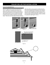
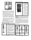
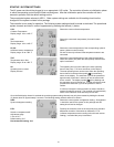
Remove the temperature gauges (C,E) by grasping the 2.
frame and pulling straight forward.
Remove the front cover (D) of the solar station. 3.
Remove the retainer clips behind the isolation ball 4.
valves (J, Q) with a flat head screw driver to free the
mounting plate from the station (see Figure 23).
Figure 23
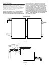
Note: To aid in later assembly, while each leg of the station
assembly is removed from the bracket, an extension leg of
¾” copper tubing can be attached to the bottom threaded
connector using the ¾” female NPT sweat adaptor
provided.
Line the mounting plate up level on the wall and mark 5.
the drill holes. (Holes will be 5 ¾” (146 mm) apart).
Drill the two holes with a 3/8” drill bit and mount the
plate with either the masonry mounting hardware or
drywall hardware provided.
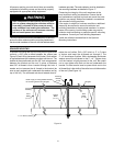
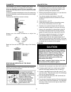
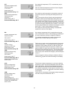
After the mounting plate is secured to the wall 6.
replace the solar pump station back cover, insert the
retaining clips half way onto the mounting retaining
stud (see Figure 24) behind the isolation ball valves
(J, Q), push the assembly onto the bracket mounting
stud and push the clip down into place. Ensure
assembly is properly locked into place.
Figure 24
Connect the stainless steel corrugated hose to the 7.
safety group (N). Do not forget to insert the seal.
Choose the position for the expansion tank bracket 8.
on the wall beside the solar pump station. Fasten
the bracket to the wall with the enclosed hardware
(masonary or drywall).
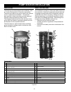
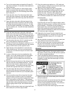
Unscrew the tank connector to separate the two 9.
halves. The top half should be pushed onto the
mounting bracket and the lock ring tightened. The
bottom half should be attachet to the ¾” threads on
the expansion tank.
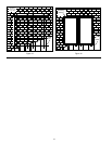
NOTE: The tank connector allows you to isolate the
expansion tank from the solar circuit (Figure 25). When
the nut is unscrewed the valves in each half of the tank
connector are automatically closed tightly by the integrated
springs. Each side remains closed until the two halves are
screwed back together and the valves are forced open.
The expansion tank should not be connected to the system
until is has been flushed and charged.
PUMP STATION INSTALLATION