


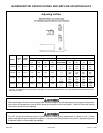


BLOWER MOTOR SPECIFICATIONS AND AIRFLOW ADJUSTING DATA
Adjusting Airflow
MODEL
MOTOR
HP
BLOWER
WHEEL
HEAT SETTINGS COOL SETTINGS
HEATING CFM @ .50 STATIC COOL CFM @ .50 STATIC
SETTING
"A"
SETTING
"B"
SETTING
"C"
SETTING
"D"
COOLING
ADJUSTMENT
SETTING
"A"
SETTING
"B"
SETTING
"C"
SETTING
"D"
AV050B3 1/2 10 X 6 525 425 325 625
NORM
( + )
( - )
1200
1380
1020
1000
1150
850
800
920
680
600
690
510
AV075B3 1/2 10 X 6 740 640 540 840
NORM
( + )
( - )
1200
1380
1020
1000
1150
850
800
920
680
600
690
510
AV100B4 3/4 12 X 9 1250 1150 1050 1350
NORM
( + )
( - )
1600
1800
1360
1400
1610
1190
1200
1380
1020
1000
1150
850
AV125B5 3/4 12 X 12 1650 1550 1450 1750
NORM
( + )
( - )
2000
2200
1700
1800
2070
1530
1600
1840
1360
1400
1610
1190
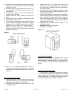
THE UNIT, AS SHIPPED, IS FACTORY SET AT SETTING "A" TO RUN AT THE MIDDLE OF THE HEATING RISE RANGE SHOWN ON THE
UNIT RATING LABEL.
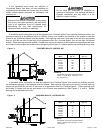
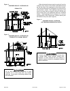
When operating the furnace in the heating mode, the static pressure and the temperature rise (supply air temperature
minus return air temperature) must be within those limits specified on the rating label. Failure to follow this warning
could lead to severe furnace damage.
Turn OFF all gas and electrical power to furnace before performing any maintenance or service on unit. (Unless
specific test requires gas and electrical supplies.) Failure to take this precaution may result in personal injury due
to electrical shock or uncontrolled gas leakage.
20571201 Issue 0527 Page 4 of 28